LIS3DH Hookup Guide
 MTaylor
Hardware Overview and Assembly
There are a few different methods with which you can use the LIS3DH.
The top side of the board has the LIS3DH sensor, some bypass caps and pull-up resistors.
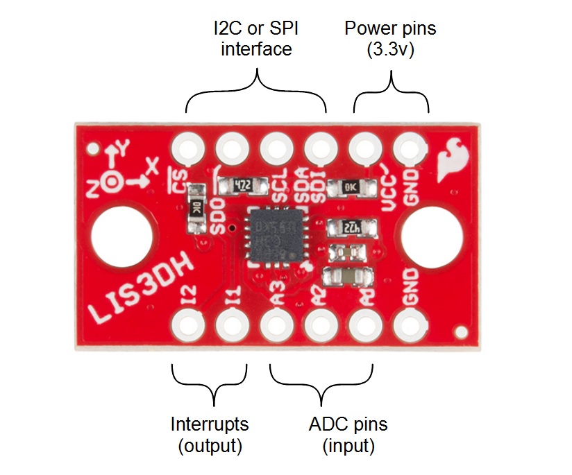
This table gives more information as to each pins functionality. The serial port can be connected as either SPI or I2C, and it uses the same physical pins for both. To get going, just wire up your choice of interface, supply 3.3v, and ground. Note that you will not need to use all the pins no matter which communication method you choose.
| Connection | |||||
|---|---|---|---|---|---|
| Group | Name | Direction | Description | I2C | SPI |
| Serial | !CS | I | Chip select (for SPI) | NC | !CS |
| SDO | O | Data output (MISO for SPI) | NC | MISO | |
| SCL | I | Data clock | SCL | SCK | |
| SDA/SDI | I/O | Data in (SDA for I2C, MOSI for SPI) | SDA | MOSI | |
| Interrupts | I1 | O | Primary int has FIFO + motion | Optional MCU | |
| I2 | O | Secondary int has motion | Optional MCU | ||
| ADC | A1 | I | Analog in | Optional | |
| A2 | I | Analog in | Optional | ||
| A3 | I | Analog in (unused for temp readings) | Optional | ||
| Power | VCC | I | 3.3V input | Supply | |
| GND | I | Ground connection (either PTH) | Supply | ||
On the bottom, there are two jumpers that correspond to the I2C address and pull-up enable.
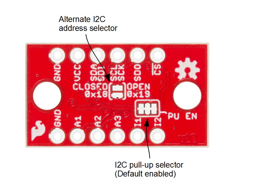
The following options are available:
- The I2C Address Jumper -- Bridge to use alternate address 0x18, otherwise leave open for 0x19. Leave open for SPI use.
- The I2C Pull-up Enable -- Closed by default, this connects a pull-up resistor between the I2C lines and VCC. This generally doesn't interfere with SPI operation, but, if less power consumption is required, carefully cut the copper traces.
Working with a Breadboard
This sensor works nicely with a breadboard for easy connection, and, because it gives some mass to the accelerometer, it more closely matches what might be expected from a project or cellphone.
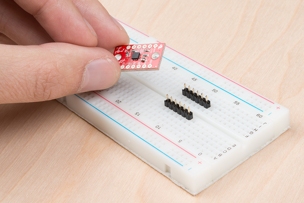
To add headers, break off two 6-pin lengths of 0.1 inch male headers, and set them into a breadboard to use as a soldering jig.
Drop the breakout board onto the pins, and solder down the rows.
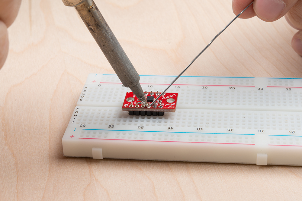
Congratulations! You're now ready to connect the sensor to a microcontroller of your choosing.