LiPo Charger Plus Hookup Guide
 Alex the Giant, Ell C
Hardware Overview
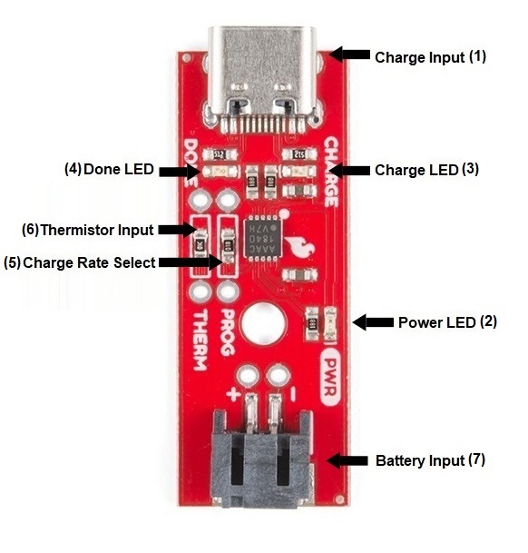
For a quick reference, here is an annotated diagram of the parts used on the LiPo Charger Plus:
| Number | Description |
| 1 | Charge Input - The input voltage for the MCP73833 charger IC is between 3.75 to 6V. To fully charge the battery, it is recommended to have a voltage around 5V. The charge IC will regulate the voltage down to safely charge the LiPo battery. |
| 2 | Power LED - When power is supplied this red LED should turn on. The LED is connected to the active low PG (power good) pin, which is active whenever the input to charger is about the UVLO (3.7V) threshold and greater than the battery voltage. |
| 3 | Charge LED - When a battery is connected and the charge controller is charging the battery, this LED will turn on, and should be off otherwise. |
| 4 | Done LED - After the battery has reached a full charge, this LED will turn on, and should be off otherwise. |
| 5 | Charge Rate Select - Programmable current regulation (default: 1kΩ). Selects the maximum amount of current to charge the battery. For a detailed explanation, see the charge rate setting section of this guide. |
| 6 | Thermistor Input - An internal 50 µA current source provides the bias for most common 10kΩ negative-temperature coefficient thermistors (NTC). The MCP73833 compares the voltage at the THERM pin to factory set thresholds of 1.20V and 0.25V, typically. If using a NTC thermistor, the 10kΩ SMD resistor should be removed. |
| 7 | Battery Input - A single-cell LiPo battery can be connected to either the JST connector, or PTH pins. If using the PTH pins, pay close attention to the polarity of the battery/battery holder, as connecting a LiPo battery backwards to the charger will destroy the IC. |
Status LEDs
The LiPo Charger Plus has three LEDs, a red LED for power, and two status LEDs. Most of the time the charge LED will turn on when the board is charging a battery, and turn off when the board is done charging. The done LED will turn off when the board is charging and turn on when done charging. For a full list of LED status indicators, refer to the table below.
| Charge Cycle State | Charge | Done | PWR |
| Shutdown | OFF | OFF | OFF |
| Standby | OFF | OFF | ON |
| Charge In Progress | ON | OFF | ON |
| Charge Complete | OFF | ON | ON |
| Temperature Fault | OFF | OFF | ON |
| Timer Fault | OFF | OFF | ON |
| System Test Mode | ON | ON | ON |
Setting a Different Charge Rate
Lithium batteries should be charged at a rate no higher than 1C (eg. a 400mAh battery should be charged no faster than 400mA). The LiPo Charger Plus has a 1kΩ SMD resistor populated, which sets the charge rate at the maximum 1000mA. If your battery is smaller than 1000mAh, this resistor should be removed and replaced with an appropriate resistor. To determine the correct resistor value, use the formula or lookup table below:

| I_REG (mA) | R_PROG (kΩ) |
| 1000 | 1.00 |
| 900 | 1.11 |
| 800 | 1.25 |
| 700 | 1.43 |
| 600 | 1.67 |
| 500 | 2.00 |
| 400 | 2.50 |
| 300 | 3.33 |
| 200 | 5.00 |
| 100 | 10.0 |
Over Temperature Protection
The MCP73833 has two forms of thermal protection, one for the charge controller itself and the other for the battery. The charge controller has an internal temperature sensor to maximize the current charge rate up to the programmed charge rate without over heating. When the die temperature of the MCP73833 reaches ~95°C, the charge controller will reduce the charge rate to prevent over heating. Over heating is most likely to occur at the beginning of a charge when the battery's voltage is the lowest. As the difference between the supply voltage and the battery voltage decreases, the die temperature will decrease and allow the charge current to increase up to the programmed charge rate.

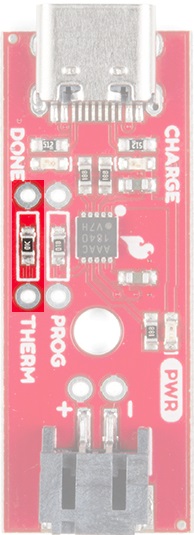
The other temperature sensor is optionally available for the battery. The MCP73833 has an input pin for a thermistor which can be attached to the battery using a high temperature tape. The thermistor that the charge controller is designed to use is a negative-temperature coefficient (NTC), which decreases it's resistance as the temperature increases. If sourcing your own NTC thermistor, look for a NTC thermistor with a resistance of 10kΩ at 25°C. To connect a NTC thermistor, remove the 10kΩ SMD resistor and solder the leads of the NTC to the PTH resistor pads highlighted below.
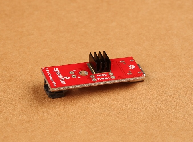
Adding a Heatsink
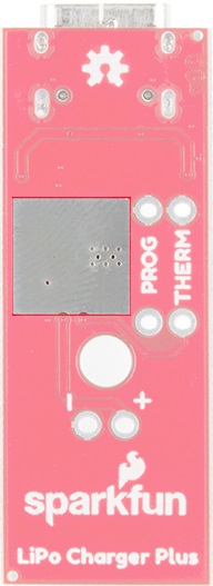
If the charge rate isn't getting up to the programmed charge rate, the IC is most likely overheating and limiting the current to the battery. One of the easiest ways to solve this is to add a heatsink with our thermal tape. On the bottom of the board is an exposed pad underneath the MCP73833.
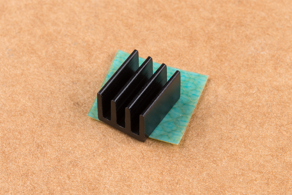
To add a heatsink first cut the thermal tape to rough size:
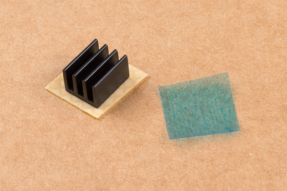
Peel off one of the protective coverings and attach heatsink to thermal tape:
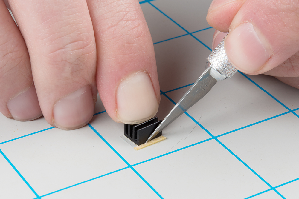
With a hobby knife, follow the perimeter of the heatsink to cut the tape to it's final size:
Remove the remaining protective covering of the tape and attach the heatsink to the exposed pad. If using a standoff, you may want to attach the standoff first to make sure you have enough clearance between the standoff and the heatsink.