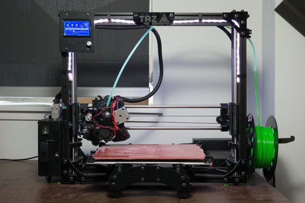
Light Up Your 3D Printer's Bed
Hardware Hookup
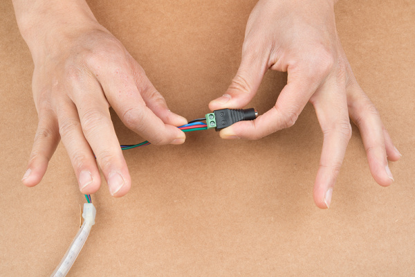
The wiring is simple between the female barrel jack adapter and the non-addressable LED strip. Simply insert the black wire connecting the "12V"" pin to the "+"" of the barrel jack adapter's screw terminal. Then insert the rest of the wires to the "--" screw terminal.
Hookup Table
Below is a hookup table that shows the connection between the female barrel jack adapter and non-addressable RGB LED strip.
| Nonaddressable RGB LED Strip Pinout | Female DC Barrel Jack Adapter |
|---|---|
| + | 12V |
| - | G |
| - | R |
| - | B |
Connecting and Modifying the LED Strip
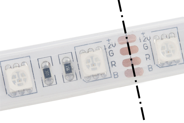
We will be attaching the LEDs to the top of the frame. Make sure that the LEDs and wires are not in the way of any moving parts. Determine the length that you need by holding the LED strip up against the 3D printer's frame. The length depends on the size of your printer's frame. For the Lulzbot TAZ 3D printers, about 16x segments of the LED strip was used. For the Lulzbot Mini, about 12x segments seemed to be sufficient. Each segment consists of 3x LEDs between the exposed copper pads.
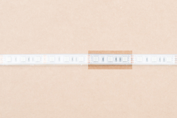
Cut 4x segments off one end of the 1M non-addressable LED using the diagonal cutter. Relative to the 3D printer that I was using, I decided to remove the 4x segments from the right side of the LED strip.
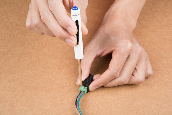
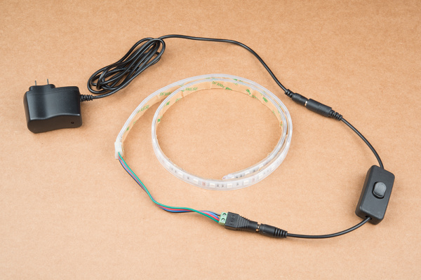
Carefully strip extra wire insulation to expose more wire for the screw terminal. You may need to tin the tips of the wires by adding more solder. Then, insert the wires for R, G, and B, into barrel jack adapter's screw terminal labeled as "--". Then tighten the screw with a Phillips head screw driver. Repeat for the black wire labeled as 12V on the "+" side.
Pull gently to verify that the wires are secure in the socket.
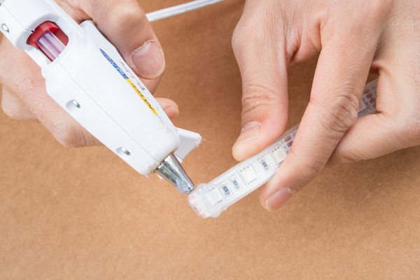
Insulate the exposed end of the LED strip with hot glue.
Connect a barrel jack power switch between barrel jack adapter and power supply.
Testing
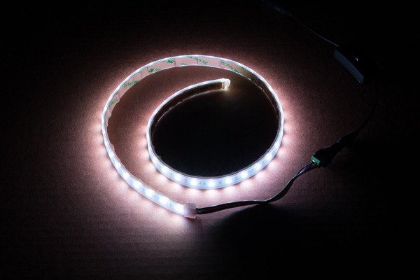
Now would be a good time to check if the hardware was wired properly. Connect the power supply to a wall outlet. If the LEDs do not light up, flip the switch to the other side to see if the LED strip lights up.
Secure the LEDs
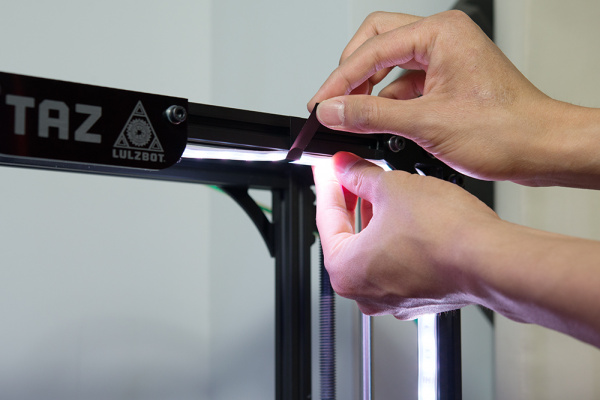
Attach the LED strip flush against the top of the 3D printer's frame and ensure that the wires are not in the way of the printable area. Since we want to illuminate the print bed, aim the LEDs toward the printer. While we could use the 3M adhesive that is on the back of the LED strip's clear jacket, I wanted to ensure that the adhesive did not fail during a print. Instead, the wires were secured by using electrical tape and wrapping the strip against the frame. Depending on the width of the tape, you may want to cut it down to prevent the LEDs from being blocked. You could use zip ties as well.
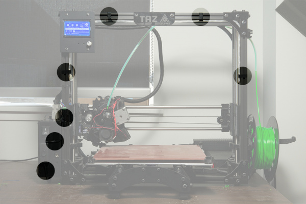
Tape was added as necessary on the enclosure; left, top, and right side of the frame as shown in the image below. Feel free to mount the power switch to another location so that you do not accidentally turn the power off to your 3D printer.
 |
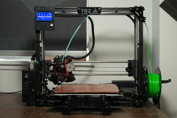 |
| Hightlighted Areas with Electrical Tape | LED Strip Mounted to 3D Printer |
Enjoy 3D Printing in the Light!
Insert the power supply into a wall outlet and flip the switch to power the lights when you need to check on your print!

