Large Solderable Breadboard Hookup Guide
 Byron J.
Quick Overview
I've used a number of similar soderable breadboards through the years, but many of them left something to be desired. The common ones are made from brittle phenolic PCB material. The copper traces are thin, poorly adhered, and tend to peel off when you rework the board. And most problematically, the trace pattern doesn't always mimic a solderless breadboard -- the power rails don't match, or the center has four holes instead of five. Moving a circuit from to the soldered board involved extra translation work.
The large solderless breadboard is intended to solve those issues. It is a real FR4 fiberglass board, with soldermask, plated through-holes, and the layout duplicates the connectivity of a solderless breadboard.
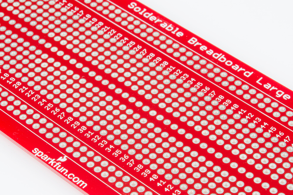
The center area of the breadboard mimics the hookup pattern of the solderless board - twin rows of 5 holes each, spaced 0.3" apart, to accommodate DIP ICs. Like the equivalent solderless board, the solderable board has 63 columns. The row and column coordinates are labeled to match the solderless boards.
Compared to the solderless boards, this solderable board also offers more flexiblity in how the power supplies can be wired.
Power Supply Background
A typical power supply provides a number of voltages to the attached circuitry. Each voltage is often referred to as a rail. * The number of supply rails needed, and the voltages provided on each, depend on the sort of circuitry being deployed.
- To begin, every power supply has a "ground" rail. Ground is used as a 0V reference point, the voltage against which the others will be measured; it may not actually be connected to Earth.
- For many years, digital circuits used a single 5V rail. More recently, lower supply voltages have become common, primarily 3.3V, but sometimes even lower, such as 1.8V.
- Analog designs frequently use higher voltage bipolar power supplies, which provide mirror-image positive and negative rails. +/-12V and +/-15V are both common.
- A mixed signal design involves both analog and digital sections, and brings along the supply voltage requirements form each. A good example would be a PC power supply, that provides 3.3V and 5V for the digital logic, and +/-12V for things like disk drive motors and cooling fans.
On a solderless breadboard, there are usually a pair of supply rails at each edge, that run the length of the board (though sometimes they aren't totally continuous, split at the halfway point). They're frequently marked with "+" and "-" symbols, possibly also color coded red and blue. The breadboard doesn't make any assumptions about how the rails get used -- it's up to the user to feed voltages to the rails.
So with that, lets explore how to configure the supply rails on this breadboard.
* I'm having trouble finding a definitive etymology, but I believe the "rail" term stems from the use of the "third rail" to supply voltage on an electric railway, a usage that dates back to the 1880's.