Large Solderable Breadboard Hookup Guide
 Byron J.
Optional Jumpers
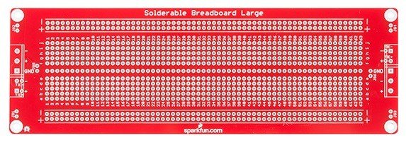
With no further configuration, this board has 5 traces that run the length of the board. Four of them are the + and - traces at the top and bottom edges of the board, duplicating the equivalent points on a solderless board. The fifth of these traces runs down the "gutter" at the center of the board, intended for use as a ground.
These 5 traces meet with 5-pin 5mm screw terminals at each end of the board. The order of the terminals matches the order of the traces across the board. As seen below, the top screw terminal pin connects to the top "-" rail, the next screw terminal down meets the top "+" rail, and so on.
The board can be adapted with wire jumpers to accommodate a number of different voltage rail combinations.
The jumpers are as follows
- JG1, JG2, JG3, JG4 can be populated to tie the mounting holes to the ground trace. If you are mounting the board in a metal enclosure, it's good practice to ground the enclosure, and join the circuit ground to the enclosure.
- JG5 and JG6 can be used to join the - rails at the edges of the board to the ground track down the center of the board.
- TIE+ and TIE- connect the + and - rails on each side of the board, respectively. Just like a solderless board, these aren't connected by default, but this board provides an easier option to tie them together.
The board also accepts screw 5mm terminals for the power connections, which can be populated to match the rail configuration. If you'd prefer a more solid connection than screw terminals provide, you can also solder wire directly to the pads.
The power connections and jumpers are duplicated at each end of the board. In most applications, you'll only need to use the connections at one end.