Solderless breadboards are great for prototyping. But they're not exactly mechanically robust. It seems like something, somewhere is always coming loose. Having a solderable board with a matching trace pattern allows you to make a prototype more solid without having to lay out a custom PCB.
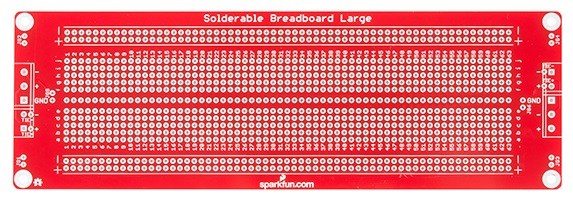
At first glance, the large solderable breadboard mirrors the hole pattern of a regular large solderless breadboard. However, on closer inspection, you'll find that it has some extra features that should ease the transition from solderless to solderable board.
In this tutorial, we'll go over the features of the soderable breadboard, show you how to use it as the most basic level, and then show you more advanced examples.
I've used a number of similar soderable breadboards through the years, but many of them left something to be desired. The common ones are made from brittle phenolic PCB material. The copper traces are thin, poorly adhered, and tend to peel off when you rework the board. And most problematically, the trace pattern doesn't always mimic a solderless breadboard -- the power rails don't match, or the center has four holes instead of five. Moving a circuit from to the soldered board involved extra translation work.
The large solderless breadboard is intended to solve those issues. It is a real FR4 fiberglass board, with soldermask, plated through-holes, and the layout duplicates the connectivity of a solderless breadboard.
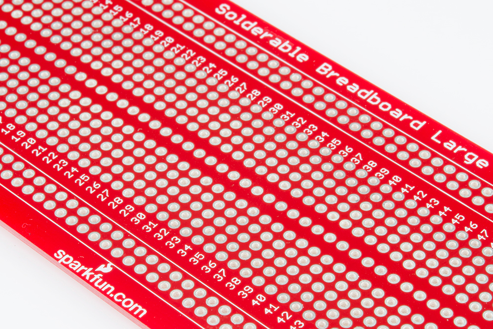
The center area of the breadboard mimics the hookup pattern of the solderless board - twin rows of 5 holes each, spaced 0.3" apart, to accommodate DIP ICs. Like the equivalent solderless board, the solderable board has 63 columns. The row and column coordinates are labeled to match the solderless boards.
Compared to the solderless boards, this solderable board also offers more flexiblity in how the power supplies can be wired.
A typical power supply provides a number of voltages to the attached circuitry. Each voltage is often referred to as a rail. * The number of supply rails needed, and the voltages provided on each, depend on the sort of circuitry being deployed.
On a solderless breadboard, there are usually a pair of supply rails at each edge, that run the length of the board (though sometimes they aren't totally continuous, split at the halfway point). They're frequently marked with "+" and "-" symbols, possibly also color coded red and blue. The breadboard doesn't make any assumptions about how the rails get used -- it's up to the user to feed voltages to the rails.
So with that, lets explore how to configure the supply rails on this breadboard.
* I'm having trouble finding a definitive etymology, but I believe the "rail" term stems from the use of the "third rail" to supply voltage on an electric railway, a usage that dates back to the 1880's.
With no further configuration, this board has 5 traces that run the length of the board. Four of them are the + and - traces at the top and bottom edges of the board, duplicating the equivalent points on a solderless board. The fifth of these traces runs down the "gutter" at the center of the board, intended for use as a ground.
These 5 traces meet with 5-pin 5mm screw terminals at each end of the board. The order of the terminals matches the order of the traces across the board. As seen below, the top screw terminal pin connects to the top "-" rail, the next screw terminal down meets the top "+" rail, and so on.
The board can be adapted with wire jumpers to accommodate a number of different voltage rail combinations.
The jumpers are as follows
The board also accepts screw 5mm terminals for the power connections, which can be populated to match the rail configuration. If you'd prefer a more solid connection than screw terminals provide, you can also solder wire directly to the pads.
The power connections and jumpers are duplicated at each end of the board. In most applications, you'll only need to use the connections at one end.
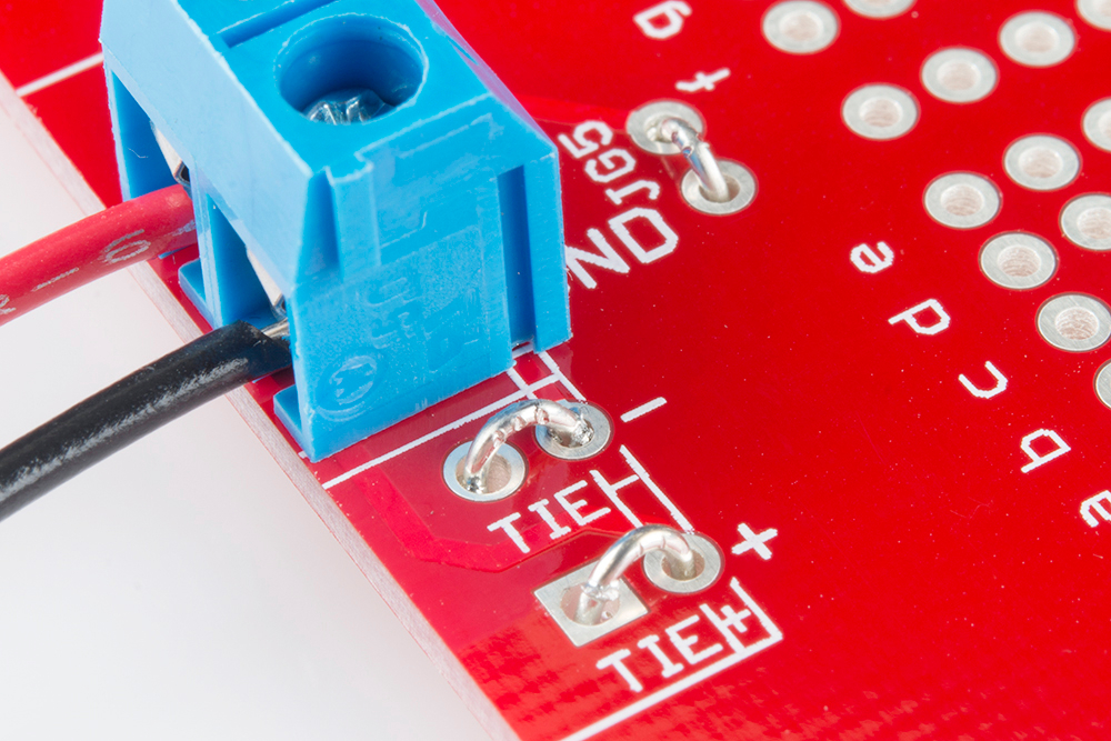
If you're building a digital circuit with a single supply rail (typically 3.3V or 5V), make the following connections
When you install components, they can pick up the supply voltage on either + rail, and ground on the - rails or at the center ground trace.
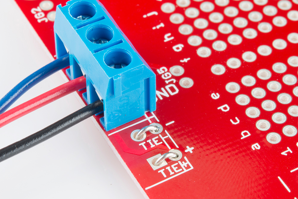
For an analog circuit with a bipolar power supply, configure the jumpers as follows
Components can pick up the positive supply voltage on either + rail, the negative supply voltage on either - rail, and ground on the center trace.
If you're building a larger circuit using more than one of these boards, they can share a power supply. The most common configuration is known as "star power distribution." The power supply forms the center of the system, and each board is connected directly to it.
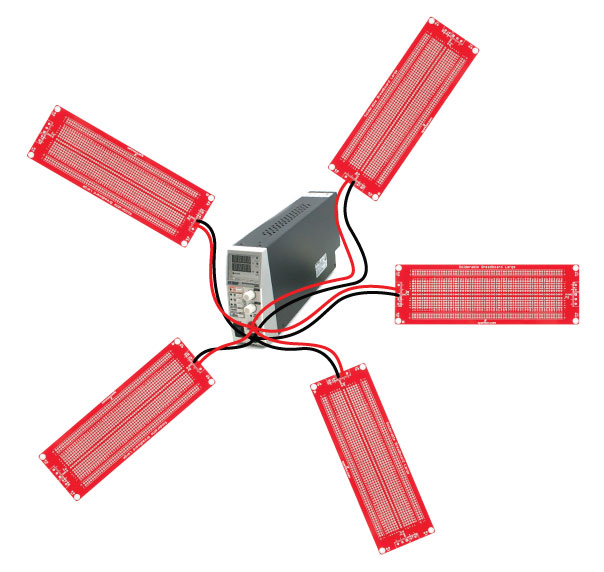
Or, redrawn for simplicity.
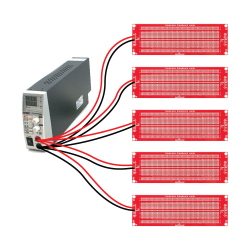
This configuration makes a direct connection between the supply and each board.
Just having these boards around makes me want to solder something. Maybe a nice Moog Filter?
For smaller prototypes, the Medium Solderable Breadboard is a smaller version of this board that pairs with the 30-row solderless breadboard.
For more information on the large soderable breadboard, visit its GitHub repository.
For more prototyping goodness, check out these other SparkFun tutorials.
learn.sparkfun.com | CC BY-SA 3.0 | SparkFun Electronics | Niwot, Colorado