IMU Data to Motion: Tutorial for Translating Sensor Data into Real-World Movement
Introduction
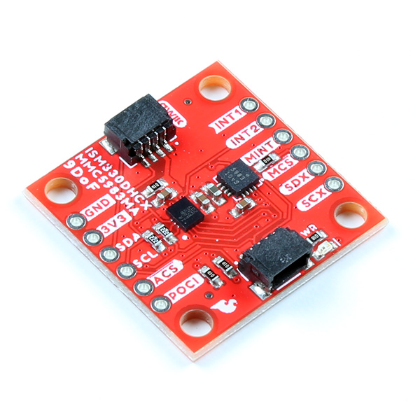
Over the Years, we’ve carried quite a number of IMUs. And why not? Inertial Motion Units are used in an incredibly broad array of products, from robots to rockets, smart watches to structural components, electronic stabilization systems to exoskeletons. IMUs combine several sensors to provide data about movement and orientation in three-dimensional space, utilizing an accelerometer and gyroscope in the case of a 6DoF sensor (six degrees of freedom), or an accelerometer, gyroscope, and magnetometer in the case of a 9DoF (nine degrees of freedom).
The Challenge: Translating Measured Movement to Motion
Monitoring and measuring this incoming data is simple, especially with our Qwiic sensors and example sketches. But let’s face it, we want to do more with our incoming motion data than just read the results on a screen. So I decided to revisit an old project build that I quickly threw together for a new product demo. Since I’ll only be using the measurements from one of the three possible sensors on a 9D0F IMU, for this project I’m going to be using one of our newer, smaller magnetometer boards to control a pair of servos, and then toss out some ideas to upgrade to a much bigger, cooler project.
Components Required
You can opt for a number of different servos, or a number of different microcontrollers, but here are some suggestions for a fast and simple demo.
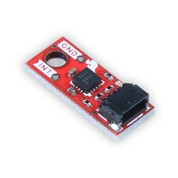
The magnetometer - SparkFun Micro Magnetometer - MMC5983MA (Qwiic)
A microcontroller - SparkFun Redboard Qwiic
2 Servos (anything from sub-micro to giant) - Generic sub-micro servo
Power Supply for Servos (optional). Power Supplies
SparkFun Qwiic Connectors - SparkFun Qwiic Cable Kit
The Project
I’ve always been a fan of flying, and eventually of flight simulators. So of course, I’ve always wanted to build a chair frame that would move in concert with the movements of my onscreen plane, whether it’s a Cessna 172 or a Airbus H225 helicopter. So in order to do this, I want to read the movement or position of our yolk or stick. Note: I know that when it actually comes to creating a chair frame that moves based on the movement of the flight stick, the movements will need to be measured from local axes, and a magnetometer, like I’m using in this example, bases its measurements on global axes. This is just a broad look at how to translate sensor data into motion, and can then be tailored to fit the needs of each project. Planes use cables to control the ailerons and elevator, and if you’re planning on building an experimental aircraft, I’m going to suggest not using this method., but if something goes wrong on a Flight Sim build, a catastrophic control failure would, at worst, toss toss onto the floor.
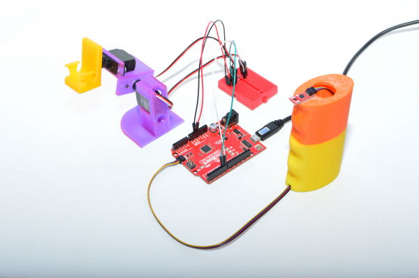
For testing the concept, I’m going to translate the sensor data to a pair of small servos. I 3D printed a small rig and a tiny chair for my little lego fly-boy. The initial concept worked just fine, I only needed to tweak the limits of the servo travel.
Hardware Setup
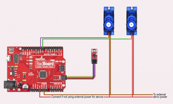
Connecting the MMC5983MA Sensor: Connect the MMC5983MA sensor to the Arduino using the SparkFun Qwiic Connectors. Plug the Qwiic connector on the MMC5983MA into one of the Qwiic ports on the Qwiic Shield or directly on a Qwiic-compatible Arduino board.
Connecting the Servos: Servo 1 Signal to Pin 8 on Arduino Servo 2 Signal to Pin 9 on Arduino Servo Power (VCC) to an external 5V power supply (opt) Servo Ground (GND) to Arduino GND
Arduino Sketch
/*
Movement to Motion: Using the SparkFun Micro Magnetometer (MMC5983MA) to control servo motors
By: Rob Reynolds
SparkFun Electronics
Date: September 19th, 2024
Based on original code by Nathan Seidle and Ricardo Ramos
License: SparkFun code, firmware, and software is released under the MIT License(http://opensource.org/licenses/MIT).
Feel like supporting our work? Buy a board from SparkFun!
https://www.sparkfun.com/products/19921
This example demonstrates how to take raw X/Y/Z readings from the sensor over Qwiic
and translate them to movement through servo motors on the X and Y axes
Hardware Connections:
Plug a Qwiic cable into the sensor and a RedBoard
If you don't have a platform with a Qwiic connection use the SparkFun Qwiic Breadboard Jumper
(https://www.sparkfun.com/products/17912) Open the serial monitor at 115200 baud to see the output
*/
#include <Wire.h>
#include <SparkFun_MMC5983MA_Arduino_Library.h> //Click here to get the library: http://librarymanager/All#SparkFun_MMC5983MA
SFE_MMC5983MA myMag;
// Here's where we set up the servos
#include <Servo.h>
Servo servoPitchX; //Create object on X access
Servo servoRollY; //Create object on Y access
// initiate variables for servo positions
int rollYVal;
int pitchXVal;
void setup()
{
Serial.begin(115200);
Serial.println("Movement to Motion Example with the MMC5983MA");
Wire.begin();
if (myMag.begin() == false)
{
Serial.println("MMC5983MA did not respond - check your wiring. Freezing.");
while (true)
;
}
myMag.softReset();
Serial.println("MMC5983MA connected");
servoPitchX.attach(8);
servoRollY.attach(9);
}
void loop()
{
uint32_t currentX = 0;
uint32_t currentY = 0;
uint32_t currentZ = 0;
// This reads the X, Y and Z channels consecutively
// (Useful if you have one or more channels disabled)
currentX = myMag.getMeasurementX();
currentY = myMag.getMeasurementY();
currentZ = myMag.getMeasurementZ(); // Z axis/Yaw not needed for this example
// Or, we could read all three simultaneously
//myMag.getMeasurementXYZ(¤tX, ¤tY, ¤tZ);
Serial.print("X axis raw value: ");
Serial.print(currentX/1000);
rollYVal = map(currentX/1000, 123, 133, 15, 165);
servoRollY.write(rollYVal);
Serial.print("\tY axis raw value: ");
Serial.print(currentY/1000);
pitchXVal = map(currentY/1000, 131, 119, 35, 135);
servoPitchX.write(pitchXVal);
Serial.print("\tZ axis raw value: ");
Serial.println(currentZ); //Z values are not necessary here, unless you want to add yaw on the Z axis
Serial.println();
delay(50); // Don't overtax the I2C
}
Explanations
1. Libraries: Wire.h: For I2C communication. SparkFunLSM6DSV16X.h: To interface with the LSM6DSV16X sensor via Qwiic. Servo.h: To control the servos.
2. Setup Function: Initializes serial communication for debugging. Initializes the IMU sensor and checks if it's detected. Attaches servos to their respective pins and sets initial positions.
3. Loop Function: Reads magnetometer data (x, y, z). Maps x and y positional values to servo angles. Constrains angles to valid ranges (for this, 15-165 and 35-135 degrees). Updates servo positions based on mapped angles. Includes a small delay for stability.
Testing and Calibration:
Upload the Sketch: Connect your Arduino to your computer and upload the sketch using the Arduino IDE.
Power the Servos: Ensure the servos are powered correctly with an external power supply. (Small servos with light lode might be able to get away with using power from teh board.)
Observe Movement: Tilt or move the IMU sensor and watch how the servos react. The servos should adjust their positions based on the x and y acceleration data from the sensor.
Troubleshooting
Troubleshooting:
IMU Not Detected: Ensure the Qwiic connections are secure and that the sensor is properly connected to the I2C bus. Check if the Qwiic shield or board is functioning correctly.
Servo Movement Issues: Verify that the mapping and constraints are correct. Make sure the servo power supply is adequate. By following this tutorial, you should be able to easily interface the SparkFun Micro 6DoF IMU Breakout - LSM6DSV16X with your Arduino using Qwiic connectors and control servos based on the sensor’s motion data.
Going Further
There are a million ways to take IMU data and translate it into motion. Hopefully this gives you a look into how easy it is to get started, and inspires you to build on this simple tutorial to create your own moving masterpiece. Happy Hacking!!
