HIH-4030 Humidity Sensor Hookup Guide
Hardware Hookup
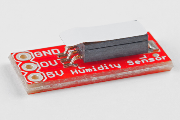
This product comes with the HIH-4030 soldered onto the breakout board. The pins of the 3-pin header are spaced by 0.1".
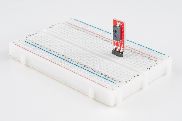
Before you can insert the HIH-4030 Breakout into a breadboard, you'll need to solder either wires or a 3-pin header to the GND, OUT, and 5V on-board connections. If you plan on breadboarding, we recommend straight male headers. Here, right angle headers were used, which is another viable option.
Example Circuit with HIH-4030 Only
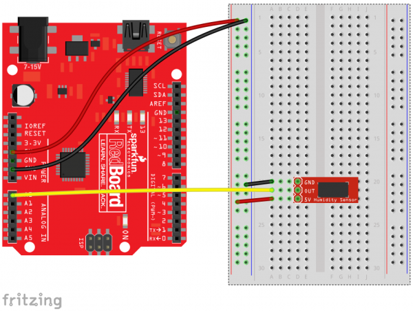
With the HIH-4030 Breakout, all you need is three wires between your microcontroller and the breakout board: Power, Ground, and Analog Output. This is a simplified circuit that should only be used to get your Humidity Sensor up and running. Here is an example hookup diagram demonstrating how to connect the board up to a SparkFun RedBoard:
Example Circuit with TMP102 Temperature Sensor
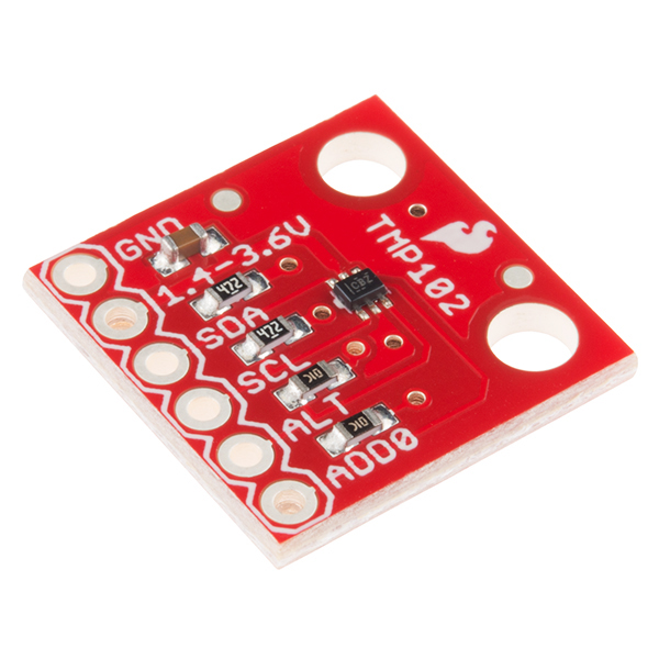
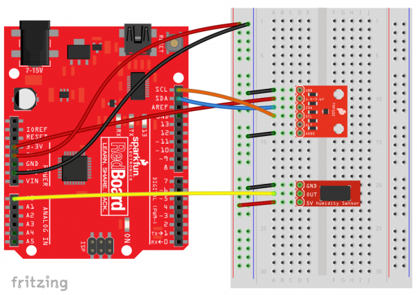
Determining Relative Humidity (RH%) requires knowing an accurate temperature. The previous circuit example does not utilize this feature, therefore, it will be necessary to to use your HIH-4030 Breakout in conjunction with a Temperature Sensor. For this Hookup Guide, we have used the TMP102 Breakout.
The TMP102 is a digital sensor that communicates over I2C, has a resolution of 0.0625°C, and is accurate up to 0.5°C. There is no on-board voltage regulator, so supplied voltage should be between 1.4 to 3.6V. Do not hook up the TMP102 VCC to 5V. You'll want to use 3.3V on your Arduino or SparkFun RedBoard for this connection. As an additional resource, refer to the TMP102 datasheet.
Since this is an I2C device, the connections you'll be most concerned with is the SDA (Data) and SCL (Clock) pins on either an Arduino or SparkFun RedBoard. Here is an example hookup diagram demonstrating how to connect the HIH-4030 Breakout with a TMP102 Digital Temperature Sensor board up to a SparkFun RedBoard:
