Hacking Your Maker Faire Badge
Board Overview
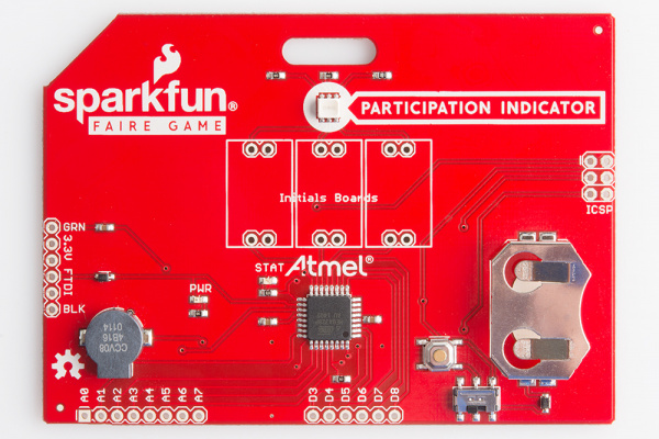
The Badge has several features you should be aware of when hacking on it.
Microcontroller
The IC on this board is the ATMega328. This is the same chip that runs the Arduino Uno, and several of our LilyPad boards. However, this board relies on the internal oscillator of the 328, instead of having an external crystal like the Uno or LilyPad main board.
Power System
The board has a battery holder for a 3V, 20mm coin cell battery. We recommend using the CR2032, as this has a higher capacity of 250mAh at 3V. The ON/OFF switch at the bottom of the board enables the user to turn off the battery supply when the badge is not in use.
The board can also be powered off of the 3.3V and GND pins on the FTDI header on the left side of the board. This is not connected in any way to the ON/OFF switch, so the board will run as long as this is connected.
Communication
There are several methods of communicating with your badge. The first is the FTDI header on the left hand side of the board. The board mates with a 3.3V FTDI Breakout Board, which enables you to communicate via serial over a USB interface to the board.
You can also communicate or program the board via the ICSP header on the right side of the board. This will communicate with the board using SPI protocol.
Participation Indicator
This is an RGB LED, located in the top center of the board (right where the lovely silk label points!). The board comes pre-programmed with this LED functioning as a participation indicator for our #makergame, but you can use this for any purpose you so desire. The blue channel of the LED is connected to pin D9 on the ATMega328, the red channel connects to pin D10, and the green channel connects to pin D11/MOSI. Keep this in mind if you decide to use the ICSP header for hacking your badge later - use of the MOSI line will restrict your ability to use the green channel on the LED.
The three pins to which the LED connects are capable of pulse-width-modulation (PWM) control, so this is a nice feature to be aware of when you are thinking how you would like to hack your board.
Buzzer
The buzzer is located on the left side of the board. This comes pre-programmed to act as an indicator for our #makergame, just like the LED. Again, though, just like the LED, you can reprogram your board to use this for whatever application you'd like. The buzzer is tied to D2 on the ATMega328.
Additional I/O Pins
There are 14 additional pins broken out for you, the user, to configure on your badge. Digital pins 3-8 are broken out on the bottom right side of the board. Pins 3, 5, and 8 are capable of PWM control, which makes these useful pins for things like driving servos or other small motors.
Analog pins 0-7 are broken out on the bottom left side of the board. These pins can be used for analog-to-digital conversion, and are very helpful for interfacing with sensors that have analog signal outputs.
