Hacking Your Maker Faire Badge
Assembling the Board
Now that you are familiar with the hardware available on the badge, it's time to assemble it.
We will be using male headers for this tutorial, but keep in mind that you could use female headers if you so choose.
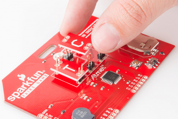
To begin, break apart six sets of 2-pin headers from the strip of male headers. Place these in the holes labeled "Initials Boards" on the top of the pcb. Then, without soldering anything, place the three initials boards onto the headers.
You want to place the initials boards before soldering to ensure everything lines up correctly and will fit together on the front of the badge. The headers will wiggle a bit doing this, so it may help to have your pcb clamped using a third hand.
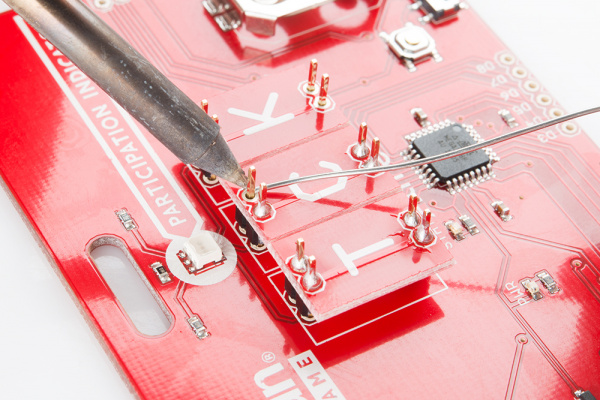
Now that you have the three initials boards lined up and placed on your badge, it's time to begin soldering. Start soldering the initials boards to the headers. Take your time and reposition the boards as needed as you go, so everything continues to line up.
Once all of the initials boards have been soldered to the headers, it's time to flip your badge over. It may be easier to only solder the back of one initials board to the badge at a time. However, since you already ensured everything will line up, this shouldn't be a problem!
These letter boards just act as jumpers between the headers, so keep in mind you could use hookup wire in place of the initials boards.
It's now time to add in additional headers. You will want to solder headers to the FTDI connection at the very least, as well as to any of the digital or analog pins broken out. If you plan on changing the bootloader on the board, you will also want to solder headers to the ICSP.
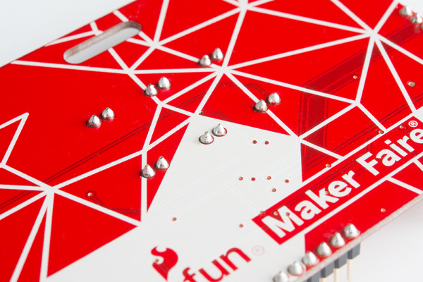
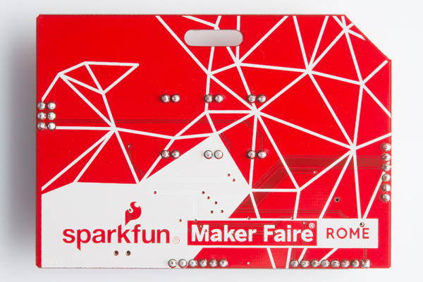
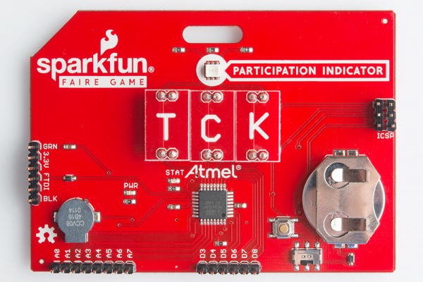
In order to allow the badge to lay relatively flat when being worn, you will want to make sure you are always soldering on the back of the badge. It should look like the picture above once you are done.
Once you have that complete, flip your badge back over and be proud of your work! Your badge is ready to act as a full Arduino and be hacked!
