Hackers in Residence - Sound and Motion Reactivity for Wearables
 matt pinner
Assembling the Hardware
Here is the hardware I ended up using in the project.
Let's go over each component in detail.
Battery Power
I love these cell phone boost charger external batteries. Having the charger, boost regulator, battery, and protection circuitry all in one packages saves a ton of time and money. You can always charge your phone from it in a pinch and carrying an extra is easy with this thin design.
Of course I have to include a Wake-on-Shake. I'm starting to put them in all my mobile projects and have all but stop using power switches to turn things off. I'd been having entirely too much fun with these.
Motion
I choose to put a combined accelerometer and gyro on board to detect certain types of motion. Specifically, I wanted to isolate when one is spinning or turning around. I find this could in the future be a compelling control signal. The up and down motion of the body could be an indicator of walking, stillness, running, or dancing.
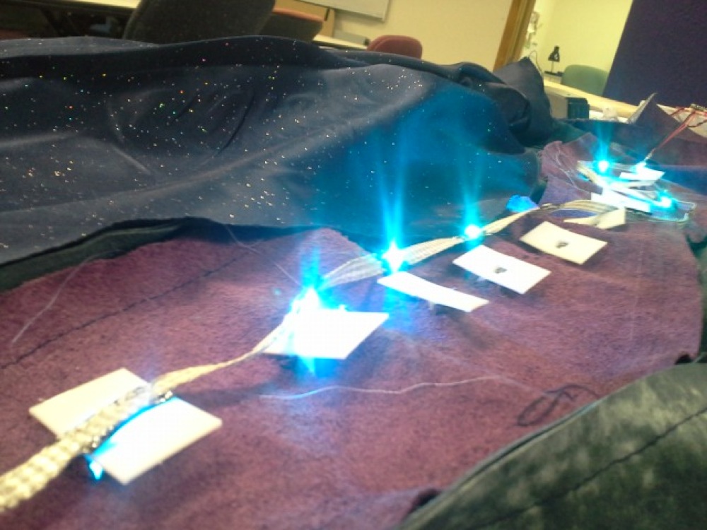
LEDs
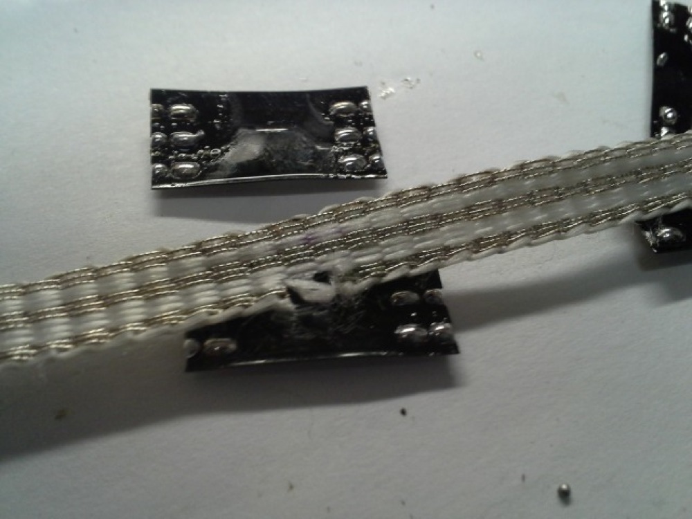
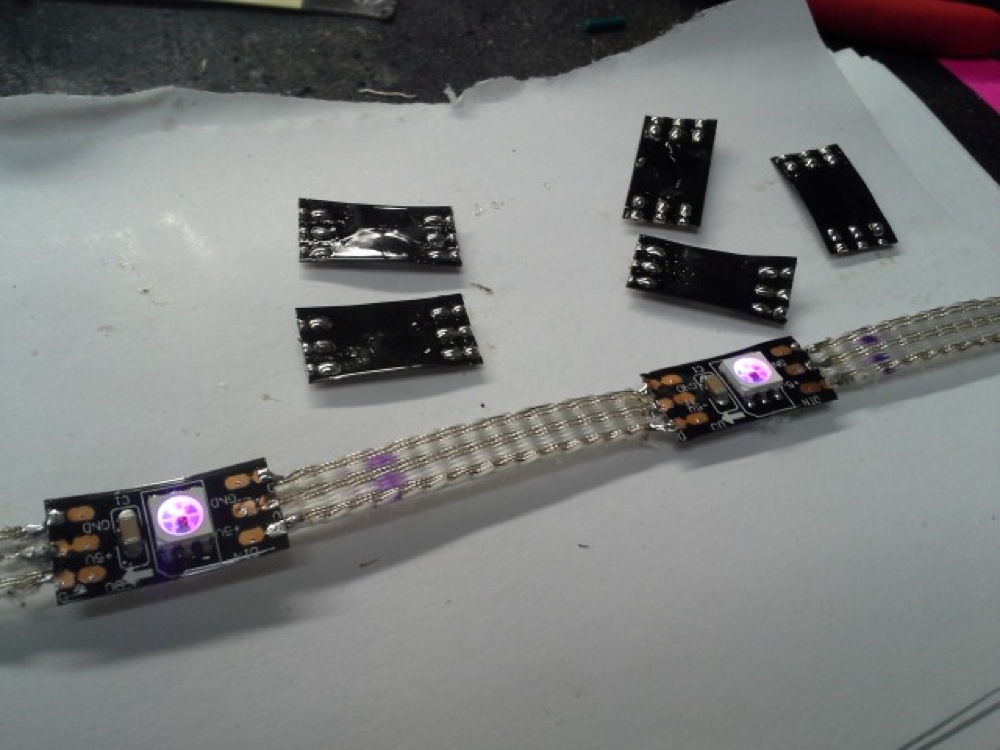
I developed a variety of techniques for mounting LEDs for wearable use. WS2812 LEDs are by far my favorite. By only needing 3 conductors, I can now use the best conductive ribbon to attach them to my jacket. Using this very flexible e-textile spine makes it much more resilient to any movements and folding that a normal garment might undergo.
I cut a small portion out of the data trace of the conductive ribbon under where I'll solder each LED. This allows the data lines to not be shared by multiple LEDs, so the signal can pass cleanly. I've started doing this a lot at Crashspace and even helped with a tutorial if you want to try sewing and wearing these NeoPixel/WS2812 style addressable strip LEDs yourself.
I ended up affixing these within a 3d printed led housing It adds some much needed diffusion and allows the LEDs to be unbuttoned should i want to wash the jacket.
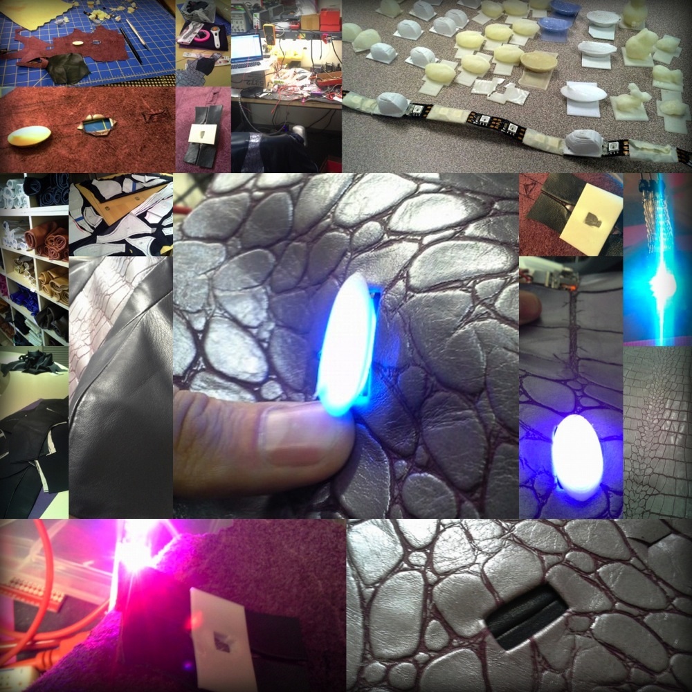
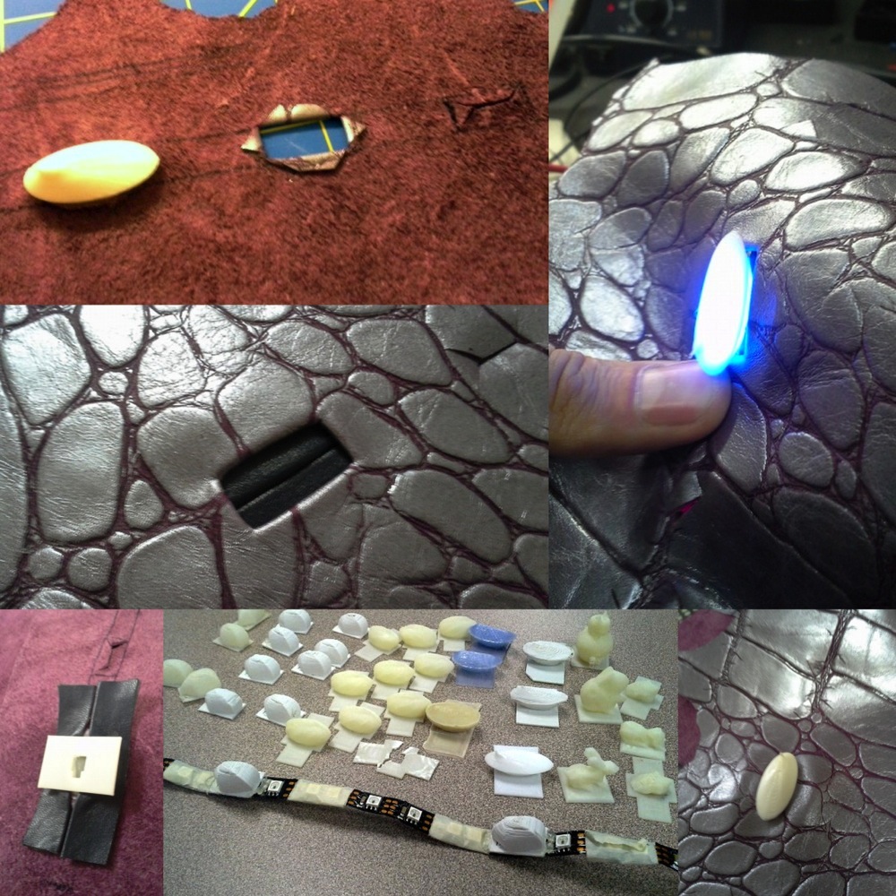
I encourage you to go more extreme with your 3d printed led diffusors, if you dare.
Sound
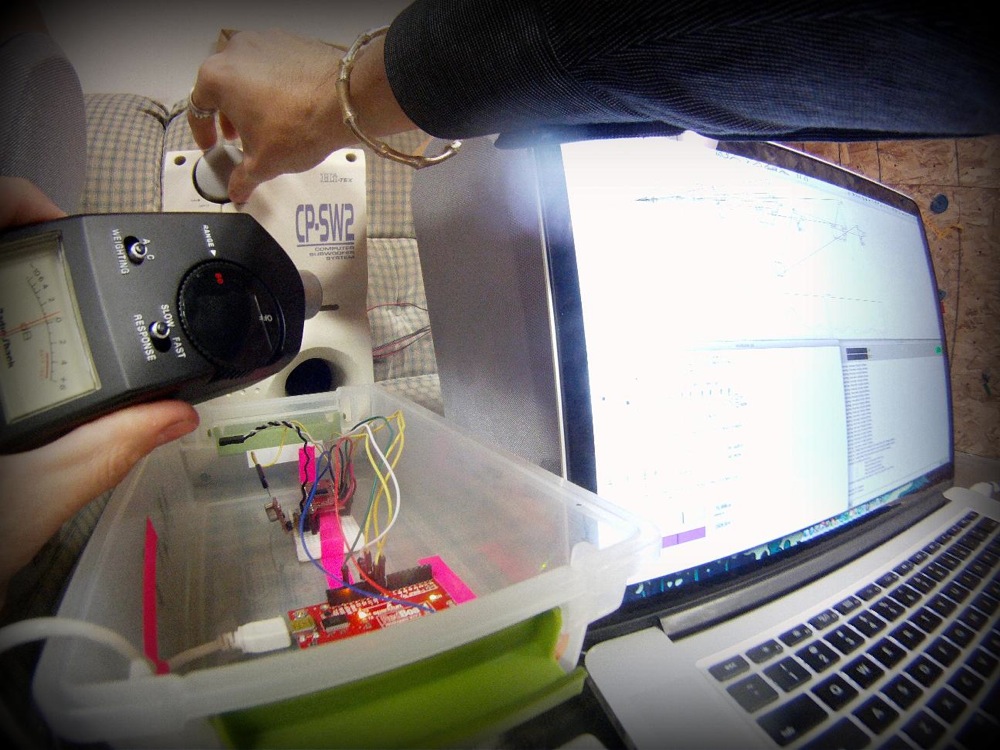
Microphones are fun! Yet, sound reactivity is hard. It is a ton of data to parse through. It takes some serious sophistication to even determine the frequency of incoming sound.
Luckily, there is help. An Arduino can determine what frequencies are present, but I found you don't get much indication of the volume within each frequency range.
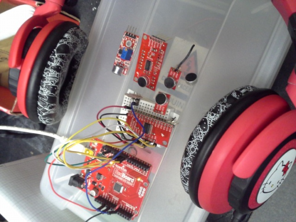
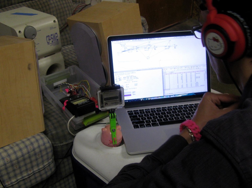
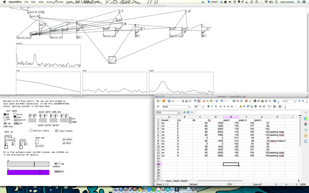
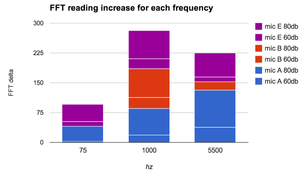
I ended up testing a bunch of microphones (and their pre-amps) to determine which would give me the most fidelity at louder volumes. Using a set of pure data patches I was able to generate tones, read the Arduino's frequency analysis, and compare.
I found the sound detector performed better overall. I love the added benefits of having the preamp broken out so it is easily tuned and the sound detection portion works very well as an additional sensor.
MSGEQ7 - Graphic Equalizer Display Filter
After digging into the microphone performance and testing the software FFT. I decided a hardware solution would make more sense. The MSGEQ7 did a much better job of analyzing the sound for various frequencies. Also, delegating this responsibility to an external piece of hardware simplifies the code and frees up my Arduino to control the lighting and analyze the motion data.
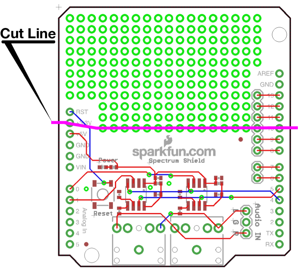
The circuit for the MSGEQ7 required some components I didn't readily have on on hand. The Spectrum Shield works very well, but it way too big to wear in any comfortable way. After consulting the eagle files, I decided the best approach it was to cut it down to a more wearable size.
At half the size it still isn't small, but it matches the size of all my other components and will now layout quite consistently within the collar.
Teensy 3.1
The Teensy is nice because you can power and program it directly from USB. This works well to get thing tested and running quickly.
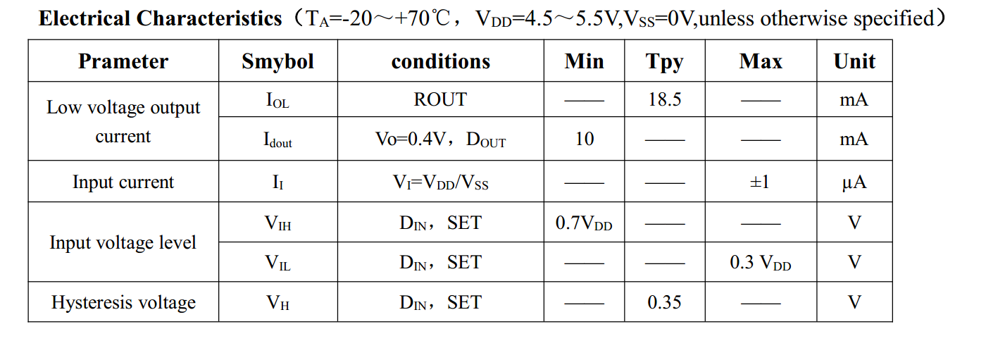
The 5v tolerant inputs of the new Teensy 3.1 are great for the audio part of this project as running my microphone at 5v gets me more range.
Ultimately, I'm happy to run a 3.3v micro to avoid all the voltage level conversion required to interface with most accelerometers.
The 3.3v logic also happens to work well enough for the ws2812/Neopixel LEDs, barely.
Using any Teensy is a bit more complex to get up and running. You need to add a bunch of configuration, code, and libraries to your Arduino IDE. Luckily there is a great installer available that make this very straight forward for any operating system.
The Teensy has very recently added some audio offerings, which I may utilize to replace the msgeq7 portion of this project.