Hacker in Residence: The Harmonic Skew Zoetrope
Hardware Assembly
Let's take a look at some of the parts that make up the Harmonic Skew Zoetrope. But first, a public service announcement...
Traveling with Electronic Components
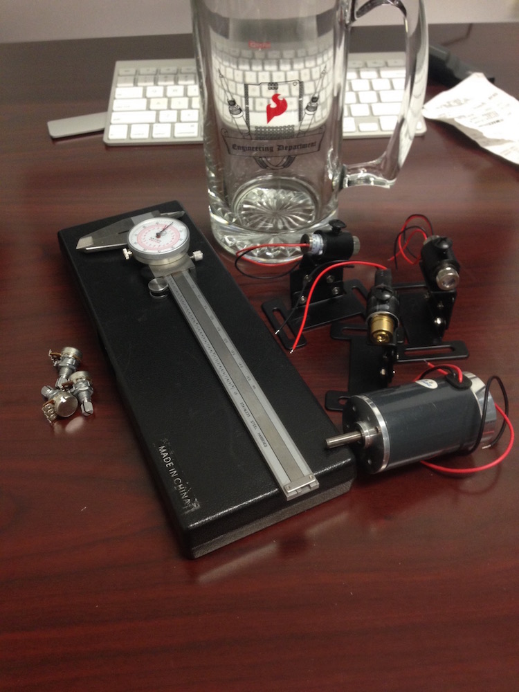
When you travel by plane with loose electronic components, be ready to answer any and all questions the TSA may have for you. Its best to keep that stuff at the top of your bag so that they don’t have to rummage around when they inevitably search your stuff. Try to stay pleasant, and try to be descriptive but not overly technical.
Eccentric Roller Assembly
The main motor is mounted with the shaft pointing up so that we can make an object oscillate in a horizontal plane. Mounted to the shaft of the motor is a piece of aluminum with the mounting hole off-center (essentially like a vibration motor). This piece of aluminum will roll inside the bore of a ball bearing, the outside of which will be mounted to a platform that will be kept from rotating by tension springs on the corners.

Depending on the size of motor and platform, a counterweight may be required to mitigate vibration.

Laser & Spinning Mirror Assembly
The cylindrical lens will bend the laser light in just one dimension, turning a point of light into a line of light. This allows us to scan the object so that the top and bottom of the object are illuminated at different points in time, but all points at the same height are illuminated at the same time.
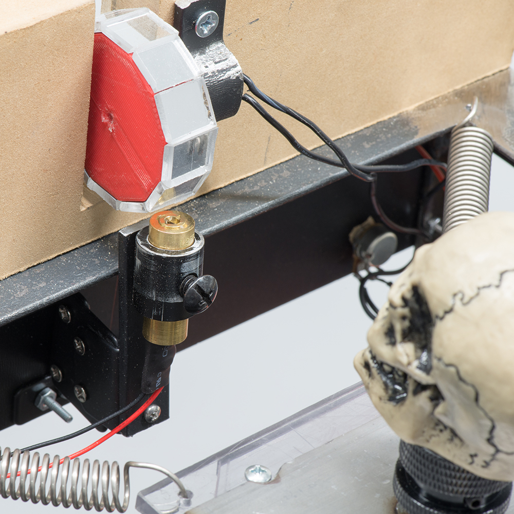
I chose to use a dodecagonal mirror (12 sides) to reflect the laser light over approximately 60 degrees. More sides will decrease the amount of area over which the laser will scan. If the laser is scanning a larger area than the object, there will be more time that the object is not illuminated, which I wanted to avoid.
Here at SparkFun, we 3D printed a dodecagonal prism shape, hot glued mirrors onto each face, and attached it to a motor.
Once the spinning mirror is mounted, the laser can be mounted so that it is reflected toward the object. The adjustable mount allows you to fine tune this position. The closer you get the laser to the mirror, the larger the area illuminated by the scanning laser.
The speed of the oscillation of the object needs to be at or near a harmonic of the laser scan frequency (which is equal to 12 times the RPM of the motor, due to the number of sides). To match these frequencies, I used a potentiometer to vary the speed of the motor that spins the mirror, but you could also use an Arduino to read and control the speeds of both motors.