GPS Logger Shield Hookup Guide
 jimblom
 Software Serial and SPI On Other Microcontrollers
Software Serial
The demo code was originally designed for the ATmega328P on the Arduino Uno. If you were using it with ATmega2560 (i.e. Arduino Mega 2560) or ATmega32U4 (i.e. Arduino Leonardo, Pro Micro 5V/16MHz, Pro Micro 3.3V/8Mhz, FioV3, etc.), you would need to re-configure the software serial pin definitions and adjust the connections. Not all the pins can support change interrupts for a serial Rx pin depending on what Arduino microcontroller is used. You will need to redefine pin definitions and reroute the connection.
For more information about the limitations, try looking at the Arduino reference language for the Software Serial library.
Redefining for Software Serial Pins
To use the GPS logger shield on an Arduino Mega 2560, you would just need to adjust the software serial pin definitions in the code where it says:
language:c
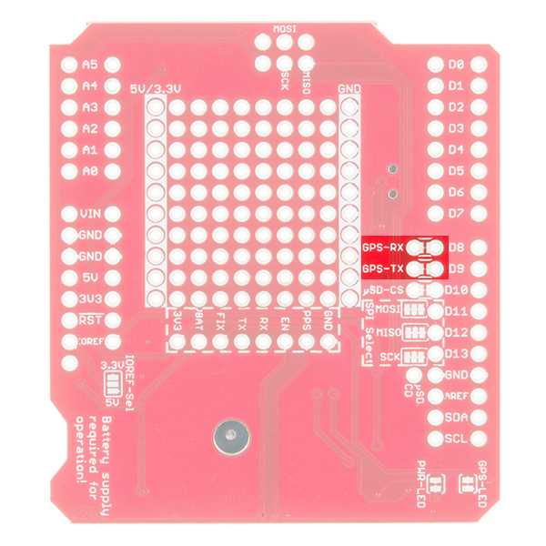
#define ARDUINO_GPS_RX 9 // Arduino RX pin connected to GPS TX
#define ARDUINO_GPS_TX 8 // Arduino TX pin connected to GPS RX
Let's change the software serial pins by using the analog pins A9 and A8, respectively.
language:c
#define ARDUINO_GPS_RX A9 // Arduino RX pin connected to GPS TX
#define ARDUINO_GPS_TX A8 // Arduino TX pin connected to GPS RX
Rerouting for Software Serial Pins
Once you adjust the code, make sure to rewire your connections. Cut across the trace between the plated through holes using a hobby knife. There is a red solder mask above the trace so make sure that the trace is completely cut.
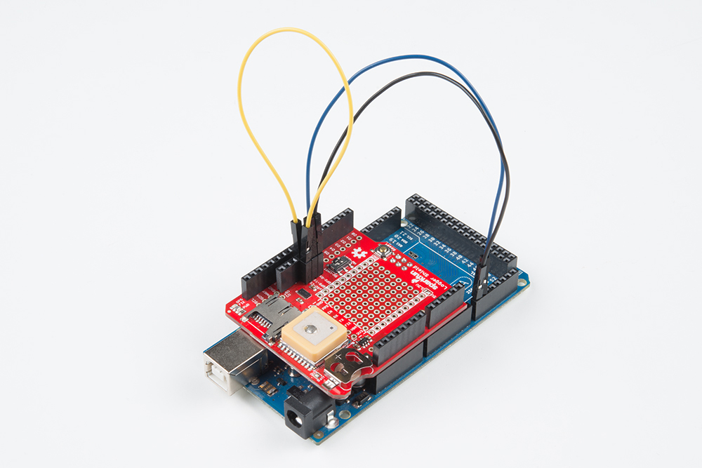
Once the trace has been cut, solder header pins or wires to the plated through holes. To easily switch between different development boards, female headers were added.

Once soldered, two male to male jumper wires were added to the through hole pins closest to GPS-Rx and GPS-Tx. With the rewired connects, GPS-Tx was rerouted to pin A9 and GPS-Rx was rerouted to pin A8. While not necessary, the yellow jumper wire was added to easily reroute the SPI's CS pin to another I/O with the data logging example.
SPI
The demo code was originally designed for the ATmega328P on the Arduino Uno. You would only need to worry about adjusting the SPI pins if you were using the CSV_Logger_TinyGPSPlus.ino logging example. Just like software serial, you would need to reroute the connection.
For more information about the limitations, try looking at the reference language for the SPI library.
Rerouting for SPI Pins
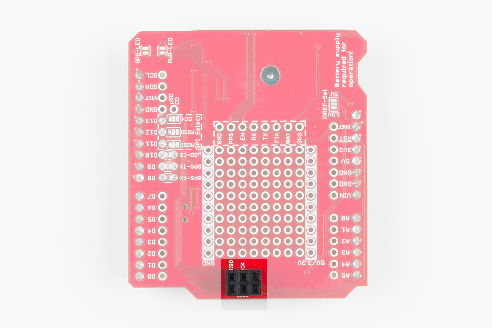
To use the GPS Logger Shield on the Arduino Mega 2560, you would just need to reroute the SPI pins. Using a hobby knife, cut the trace between the center and right pads for MOSI, MISO, and SCK.
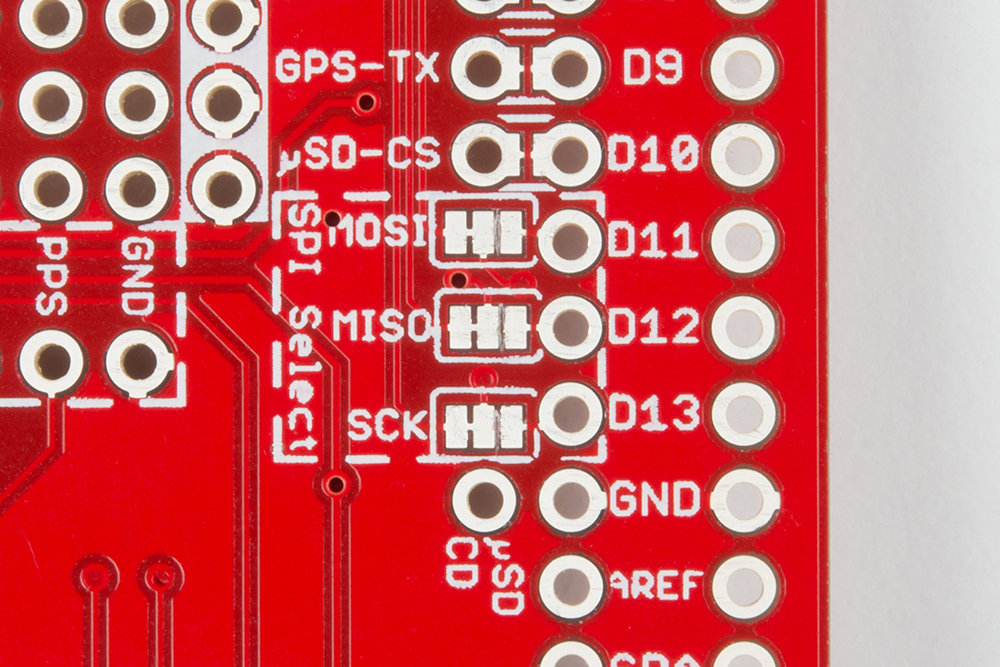
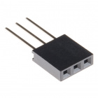
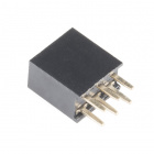
Once cut you have the option of soldering one 2x3 female header or two 1x3 stackable headers to the ICSP pins.
Make sure to solder from the top side of the shield so that the female header pins face down toward the Arduino's ICSP pins.
Once the headers are soldered, stack it on the Arduino Mega 2560 and reroute the software serial pins. The CS pin can be cut and rerouted to another pin on the microcontroller. However, the default trace on pin 10 will still work.