Getting Started with Teensy
 ishotjr
Hardware Overview
Let’s take a closer look at the Teensy 4.0 board to discover its major features. The Teensy 4.1 has a superset of these features, and its unique additional functionality will be covered in subsequent tutorials.
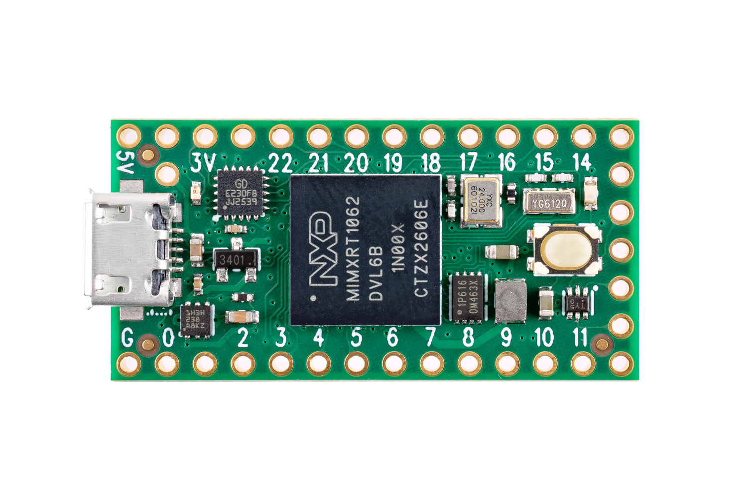
The breadboard-able pins run the length of the board. If your board came with headers installed, these pins will already be populated. If it did not, you can solder standard headers along the length of the board in order to insert the Teensy into a breadboard for prototyping. Note that the five pins on the end opposite of the board to the microUSB connector should not be populated, as this will prevent breadboard use.
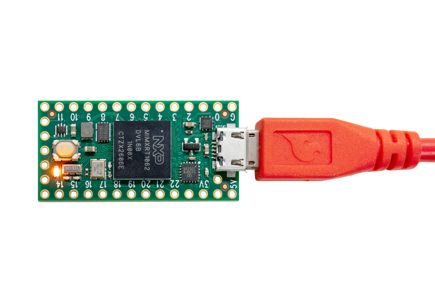
The far end of the PCB from the microUSB connector houses a single button, which is used to put the Teensy board into programming mode. A small orange LED next to the button is available to the user for indicating state and other applications. A red LED near the microUSB connector signifies that the device is in programming mode.
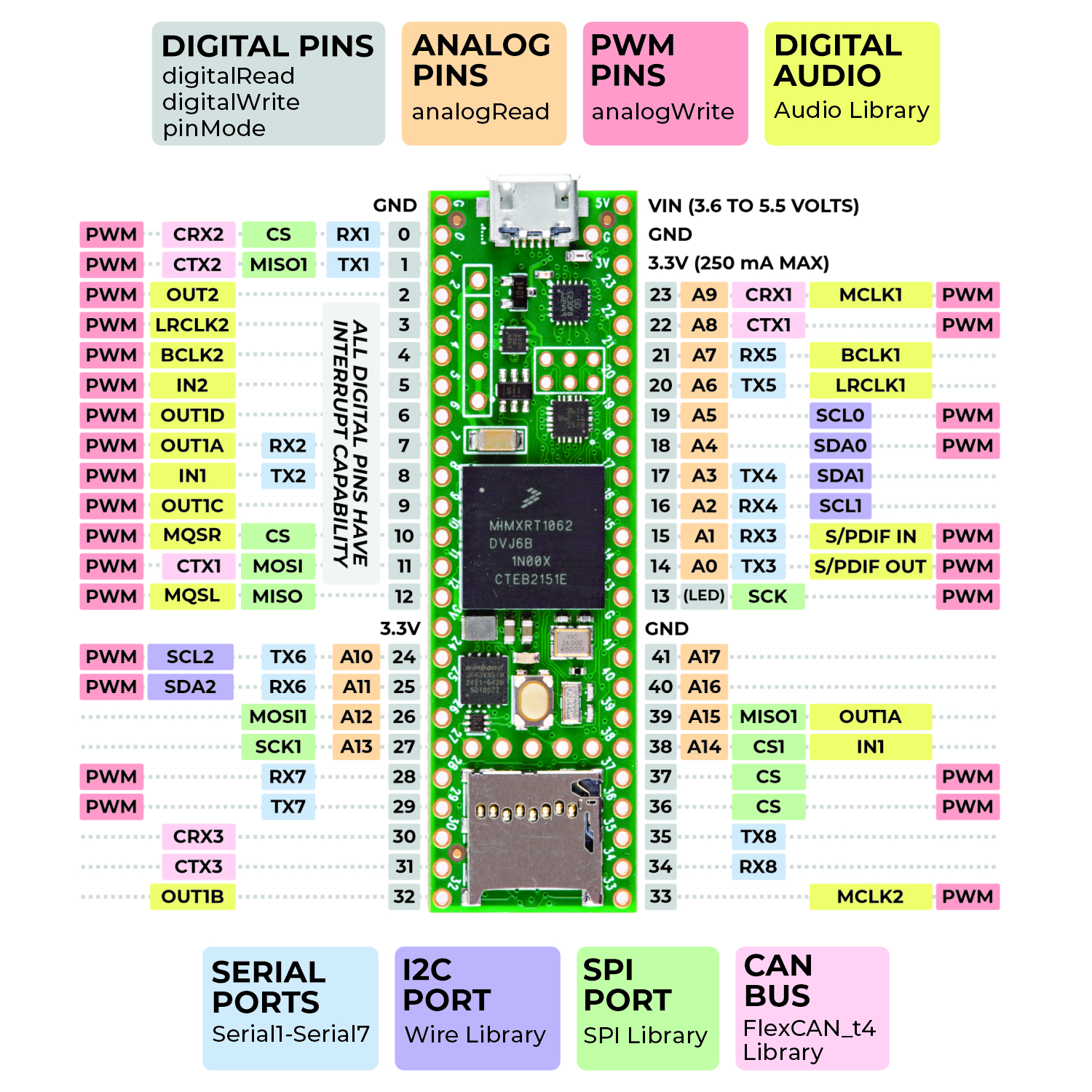
A full pinout, including the SMT pads on the reverse of the board can be found below: