Getting Started with OBD-II
 Toni_K
 Introduction
Eventually on your journey into the world of embedded electronics, you will want to "hack" a vehicle for data. As with many other integrated systems, there is a specific 'language' for talking with vehicles. This tutorial will give a basic introduction to the On-Board Diagnostics (OBD) specification that vehicles and other industrial machines use to communicate with the outside world.
Looking to get hands-on with OBD-II?
We've got you covered!
The Definition
So what exactly is the OBD specification, and why do we care? According to the Environmental Protection Agency's website:
On-Board Diagnostics, or "OBD," is a computer-based system built into all 1996 and later light-duty vehicles and trucks, as required by the Clean Air Act Amendments of 1990. OBD systems are designed to monitor the performance of some of an engine's major components including those responsible for controlling emissions.
In other words, OBD is the language of the Engine Control Unit (ECU), and it was designed to help fight emissions and engine failures.
Saving the planet is great (shout out to you citizen scientists!), but what this also means is we can access other features of the car and collect information from and on those parts. Learning how to work with those protocols also means that you can determine what that Malfunction Indicator Light (MIL) (aka the Check Engine Light) on your dash is referring to when it tells you there's an engine problem. If you or your mechanic has ever read the DTCs (Diagnostic Trouble Codes) on your vehicle, they are using OBD-II.
Unfortunately, the actual protocols themselves are not available publicly (if only they'd open source!), but we've attempted to collect and clarify as much as possible.
The Hardware
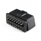
Any vehicle manufacture from 1996 or later is required by law to have the OBD-II computer system. You can access this system through the Data Link Connector (DLC). It is a 16 pin connector that can tell you which protocol your car communicates with, depending on which pins are populated in it.
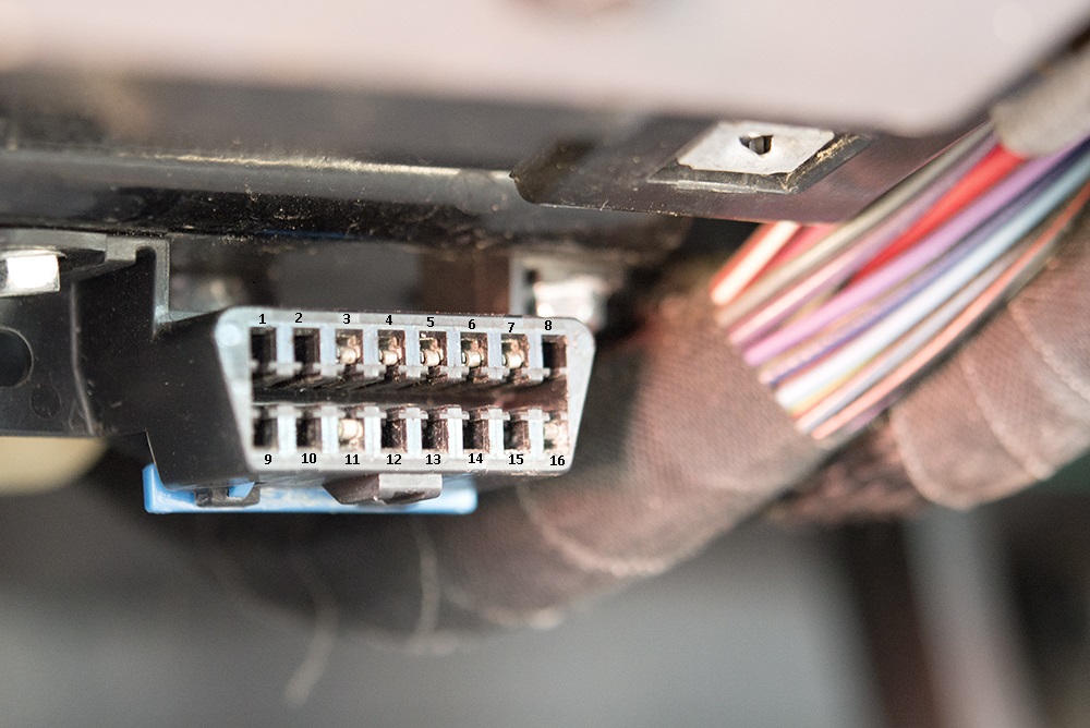
In cars, it will be located under the dash, near the driver's seat, or in the vicinity of the ashtray -- somewhere easily accessible from the driver's seat without the use of tools to access it (i.e., you don't need a screw driver to pull off a panel to get to it).
Terminology
Before we get too much farther, let's make sure we understand all the keywords used in these protocols.
Engine/Electronic Control Unit (ECU)
The ECU can refer to a single module or a collection of modules. These are the brains of the vehicle. They monitor and control many functions of the car. These can be standard from the manufacturer, reprogrammable, or have the capability of being daisy-chained for multiple features. Tuning features on the ECU can allow the user to make the engine function at various performance levels and various economy levels. On new cars, these are all typically microcontrollers.
Some of the more common ECU types include:
- Engine Control Module (ECM) - This controls the actuators of the engine, affecting things like ignition timing, air to fuel ratios, and idle speeds.
- Vehicle Control Module (VCM) - Another module name that controls the engine and vehicle performance.
- Transmission Control Module (TCM) - This handles the transmission, including items like transmission fluid temperature, throttle position, and wheel speed.
- Powertrain Control Module (PCM) - Typically, a combination of an ECM and a TCM. This controls your powertrain.
- Electronic Brake Control Module (EBCM) - This controls and reads data from the anti-lock braking system (ABS).
- Body Control Module (BCM) - The module that controls vehicle body features, such as power windows, power seats, etc.
Diagnostic Trouble Code (DTC)
These codes are used to describe where an issue is occurring on the vehicle and are defined by SAE (you can find the whole spec here for a cost). These codes, can either be generic or unique to the vehicle manufacturer.
These codes take the following format:
First unit identifies the type of error code:
- Pxxxx for powertrain
- Bxxxx for body
- Cxxxx for chassis
Uxxxx for class 2 network
Second digit shows whether the code is manufacturer unique or not:
x0xxx for government-required code
x1xxx for manufacturer-specific code
Third digit shows us what system the trouble code references:
xx1xx/xx2xx show air and fuel measurements
- xx3xx shows ignition system
- xx4xx shows emissions systems
- xx5xx references speed/idle control
- xx6xx deals with computer systems
- xx7xx/xx8xx involve the transmission
xx9xx notates input/output signals and controls
Digits four and five show the specific failure code.
xxx00 to xxx99 - these are based on the systems defined in the third digit.
You can find some incomplete lists of DTCs here and here.
Parameter Identification (PID)
These are the actual meat and potatoes of the information you can pull off of an OBD-II system. The PIDs are the definitions of the different parameters you could be interested in checking out. These are similar to the third digit in the DTCs.
Not all PIDs are supported on all protocols, and there can be several unique, custom PIDs for each manufacturer. Unfortunately, these also are not generally published, so you may need to do a lot of hunting and/or reverse engineering to determine to which system each PID relates.
There are different modes available, and each mode has several options of PIDs available in that mode. For more general information on that, please check out the PID wiki page.
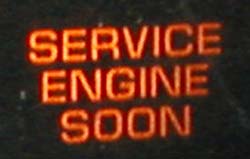
Malfunction Indicator Lamp (MIL)
The MIL is that terrible little light in the dash that indicates a problem with the car. There are a few variations, but they all indicate an error found by the OBD-II protocol.
Another possibility you might find on your dash includes this option:

No matter which one it is, these usually aren't great lights to see, unless you feel like hacking!
OBD-II Protocols
There are five different communication protocols available under the OBD-II spec. Like so many things, manufacturers tend to have their preferences and think their protocol is best, hence the variation. Here's a quick overview of each and a description of the pins used on the DLC for each.
SAE J1850 PWM
This signal is Pulse Width Modulation, which runs at 41.6 kbps. This protocol is generally used on Ford vehicles.
| Feature | Description |
|---|---|
| BUS + | Pin 2 |
| BUS - | Pin 10 |
| 12V | Pin 16 |
| GND | Pins 4, 5 |
| Bus State: | Active when BUS + is pulled HIGH, BUS - is pulled LOW |
| Maximum Signal Voltage: | 5V |
| Minimum Signal Voltage: | 0V |
| Number of bytes: | 12 |
| Bit Timing: | '1' bit - 8uS, '0' bit - 16uS, Start of Frame - 48uS |
SAE J1850 VPW
This protocol is Variable Pulse Width, which runs at 10.4 kbps. GM vehicles typically use this version.
| Feature | Description |
|---|---|
| BUS + | Pin 2 |
| 12V | Pin 16 |
| GND | Pins 4, 5 |
| Bus State: | Bus idles low |
| Maximum Signal Voltage: | +7V |
| Decision Signal Voltage: | +3.5V |
| Minimum Signal Voltage: | 0V |
| Number of bytes: | 12 |
| Bit Timing: | '1' bit -HIGH 64uS, '0' bit -HIGH 128uS, Start of Frame - HIGH 200uS |
ISO 9141-2
If you have a Chrysler, European, or Asian vehicle, this is your protocol. It runs at 10.4 kbps and is asynchronous serial communication.
| Feature | Description |
|---|---|
| K Line (bidirectional) | Pin 7 |
| L Line (unidirectional, optional) | Pin 15 |
| 12V | Pin 16 |
| GND | Pins 4, 5 |
| Bus State: | K Line idles HIGH. Bus is active when driven LOW. |
| Maximum Signal Voltage: | +12V |
| Minimum Signal Voltage: | 0V |
| Number of bytes: | Message: 260, Data: 255 |
| Bit Timing: | UART: 10400bps, 8-N-1 |
ISO 14230 KWP2000
This is the Keyword Protocol 2000, another asynchronous serial communication method that also runs at up to 10.4 kbps. This also is used on Chrsyler, European, or Asian vehicles.
| Feature | Description |
|---|---|
| K Line (bidirectional) | Pin 7 |
| L Line (unidirectional, optional) | Pin 15 |
| 12V | Pin 16 |
| GND | Pins 4, 5 |
| Bus State: | Active when driven LOW. |
| Maximum Signal Voltage: | +12V |
| Minimum Signal Voltage: | 0V |
| Number of bytes: | Data: 255 |
| Bit Timing: | UART: 10400bps, 8-N-1 |
ISO 15765 CAN
This protocol has been mandated in all vehicles sold in the US from 2008 and later. However, if you have a European car from 2003 or later, the vehicle may have CAN. It's a two-wire communication method and can run at up to 1Mbps.
| Feature | Description |
|---|---|
| CAN HIGH (CAN H) | Pin 6 |
| CAN LOW (CAN L) | Pin 14 |
| 12V | Pin 16 |
| GND | Pins 4, 5 |
| Bus State: | Active when CANH pulled HIGH, CANL pulled LOW. Idle when signals are floating. |
| CANH Signal Voltage: | +3.5V |
| CANL Signal Voltage: | +1.5V |
| Maximum Signal Voltage: | CANH = +4.5V, CANL = +2.25V |
| Minimum Signal Voltage: | CANH = +2.75V, CANL = +0.5V |
| Number of bytes: | L |
| Bit Timing: | 250kbit/sec or 500kbit/sec |
Using a Simulator
While these protocols are great for collecting data from your vehicle, it can be a real pain when prototyping to have to sit with a computer, various electronics, and cables running all over the place in the front of your car. Luckily, there are many simulators out there that allow basic prototyping and testing of OBD-II systems.
We have a few different simulators laying around here that are useful for working with these protocols. We'll update this section if/when we get our hands on any additional ones.
ECUsim 2000
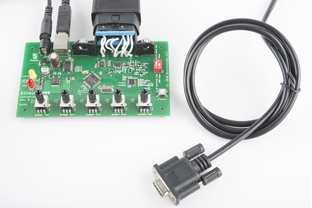
This ECU simulator is designed and manufactured by the lovely folks over at ScanTool. You can view all of the product information over at their product page here.
To get started using this simulator, you must make the following connections:
- Plug a USB cable in to the simulator and the computer. Install the necessary drivers.
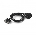
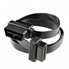
- Plug in the OBD-II cable to the simulator.
- Power your simulator off of the supplied 12V power supply.
- Open up a serial terminal at
115200 bps, 8,N,1connecting to the serial port the simulator is configured to. - Configure the simulator to the protocol you desire to test.
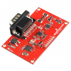
- Connect to your ECU device (OBD-II board, CAN-Bus Shield, Raspberry Pi, etc.)
Now, you can leverage the power of the simulator by verifying that the data being transmitted over the bus is what your ECU reader is receiving and vice verse.
Several different programming options are available for configuring the simulator. Check out the programming manual for more information. The version we currently have has firmware compatible with several different OBD-II protocols, which will vary depending on what you order.
The programming manual also includes all of the commands that you can use for the simulator.
For example, if we need to determine what protocol our simulator is currently set to, we would use the SPI command. In our terminal, that would look like the following:
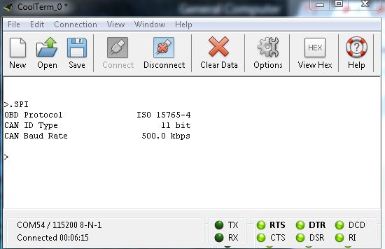
This shows that the simulator is currently set to the ISO 15765-4 protocol (a.k.a CAN), with an 11 bit ID type and is running at 500 kbps.
If you then need to send data from your simulator to a device such as the SparkFun OBD-II UART Board or CAN-Bus Shield for testing, you can use the transmit command SOMT <header>, <data>. For example, if we want to send the command that the engine fuel pressure is 100kPa, we would send SOMT followed by the Parameter ID (PID) for fuel pressure, which is 0A, and follow that with the hex value for 100 (64) in this case.
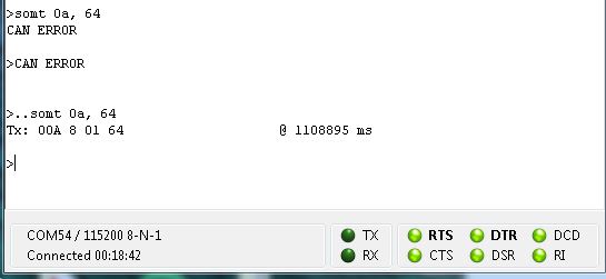
If we initially leave the connection floating (by forgetting to tighten the anchor screws on the DB9 connector) in order to simulate a connection problem, we receive the CAN ERROR message the first time we send the command. On this simulator, that means that there is a problem between the simulator and our CAN reader. Once we fix the connection however, the simulator is able to send the data, and tells us exactly what it transmitted. Pretty neat!
Resources and Going Further
Going Further
Now that you have a basic understanding of the OBD-II protocols and how to work with the various communication tools available, it's time to make your own project!
If you have any feedback, please visit the comments or contact our technical support team at TechSupport@sparkfun.com.
Additional Resources
Check out these products and projects for more OBD-II inspiration!
- OBD-II UART Board Hookup Guide
- CAN-Bus Shield Hookup Guide
- OBD-II forum
- Environmental Protection Agency's OBD Site
- SAE Standards
- National OBD Clearinghouse
- OBD Trouble Codes
- Parsing OBD-II Data Out
- freediag: Vehicle Diagnostics Suite
- pyOBD: Open-source OBD-II Diagnostics
- Windows-based Diagnostics software
- OBD Diags