Gator:control ProtoSnap Hookup Guide
 Englandsaurus
Examples
There are two ways that you can use these buttons or switches in your circuit. One would be as a part of a simple circuit, allowing the button or switch to complete and close your circuit, the other would be to use the button or switch as a digital input to control an already completed and closed circuit. We'll demonstrate these two ways to use buttons and switches by turning on an LED. For this example, we'd recommend using a gator:LED from the gator:color because you won't have to worry about a resistor.
Simple Button
In the first circuit, we'll connect a button so that it is a part of the LED circuit. We will complete the circuit by pressing down on the button. This will close the circuit so that current will flow through our button and power the LED. As soon as you stop pressing on the button, the circuit is open causing the LEDs to not light up. To set this circuit up, connect the 3V pin on your micro:bit to one side of a button, connect the other side of the button to the + side of a gator:LED, then connect the - side of the gator:LED to the ground pin on the micro:bit. The circuit should look like the below image. The connections can be seen by matching the colors of the alligator clips.
Clicking the button should turn the light on if you've set everything up properly. Instead of using the button, try using the slide switch to control the LEDs. Flipping the switch to the ON position is the same as pushing the button down. When we turn the switch to ON position, we complete the circuit by closing. Flipping the switch to the OFF position will open the circuit back up causing the LEDs to not light up. You should see the same effect with the reed switch in place of the button. To complete the circuit, place a magnet above the reed switch to close the circuit. Removing the magnet will open the circuit back up.
Digital Button
In the second circuit, we will connect our button to a digital input and our LED circuit to a digital output. Then, when we click the button, the micro:bit will see a digital signal, and it will toggle the pin for the LED circuit on. To connect this circuit, connect one side of a button or switch to the ground pin, and the other side of the button to pin 0. Now connect pin 1 to the + end of the gator:LED and the - side of the gator:LED to the ground pin on the micro:bit. Your circuit should look something like the image below.
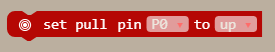
You may have noticed that we connect one end of the button to ground. This means that when we push the button, pin 0 will connect to ground and the micro:bit will read a digital low or 0 signal. However, when these digital pins are at rest, they're low, so we'll need to configure the micro:bit so that this pin rests in a high state. To do this with code, we add a pull-up resistor to pin 0 using the following block of code, located under Pins -> More -> set pull pin P0 to up.
This block will make it so that pin 0 will be a high logic level until we push our button, pulling the pin low. Now we need to have the micro:bit read the button pin to see if the button is pressed, then, using that information, decide on whether or not to turn on the light. To do this, we read the value of pin P0 into a variable named button_pin. From the Variables and Pin category, set the blocks of code to set button_pin to digital read pin P0.
Then we use an If...Else... loop to check the value of button_pin. If the value is 0, then that means the button is pressed, so we write pin P1 high. Otherwise, we write a low value to P1. Re-create the following code into your MakeCode editor or download the example by clicking the download button to test it out!
Go ahead and give your button a click. The light will still turn on, but unlike the previous example, we've done this action digitally! The example code will also work with the slide switch and reed switch. Try replacing the connection with either switch to control the LEDs.