Gas Pump Skimmers
 Nate
Nate 
Skimmer Design
Let’s dig into how these skimmers are designed...
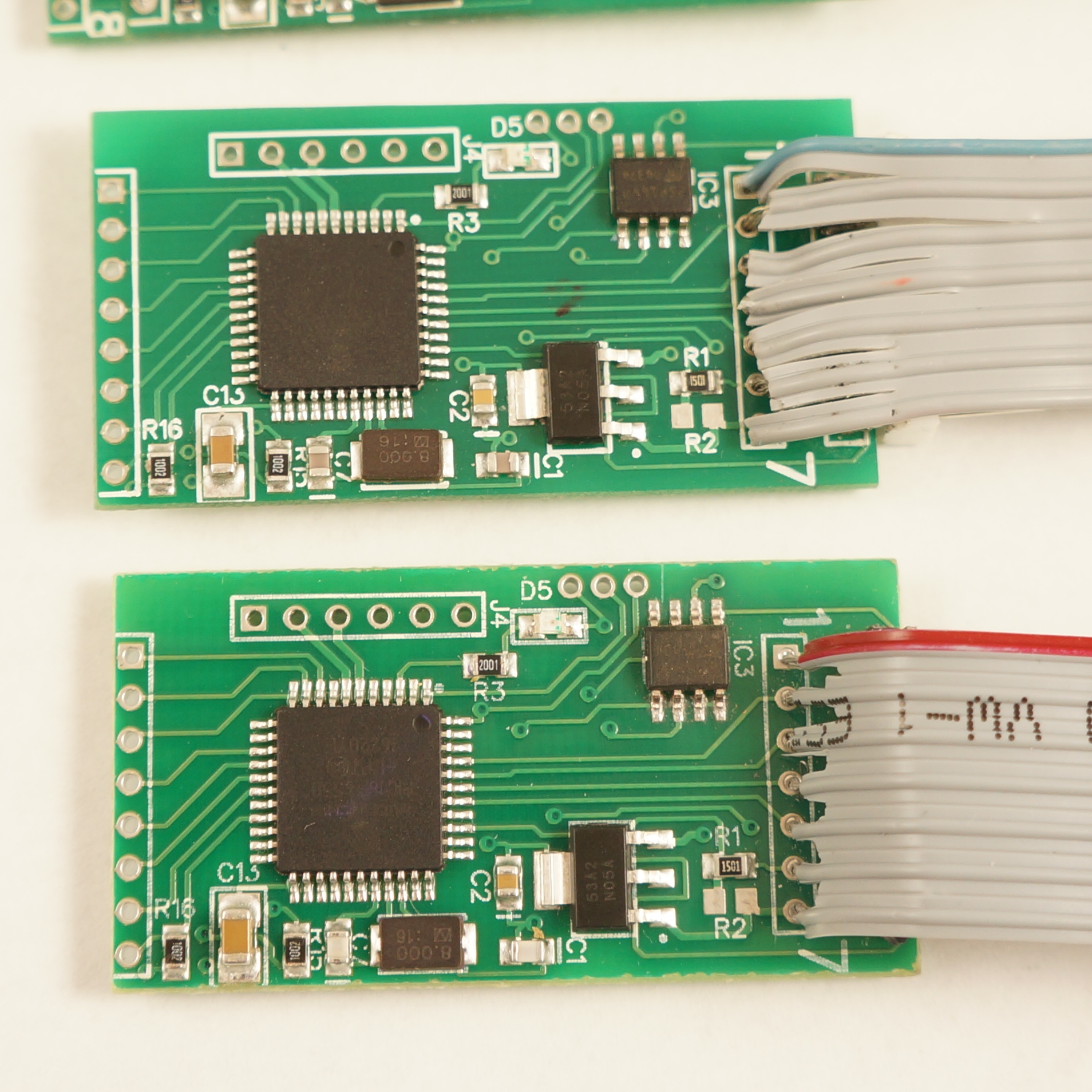
This type of skimmer seems to be very common. A quick image search shows this model all over North America.
The setup is very straight forward, but has some odd design choices. The PIC18F4550 microcontroller communicates with the Bluetooth module over serial, and also talks to an SPI Flash. Signals (serial characters) from the credit card reader are recorded by the PIC to the SPI EEPROM. When a cell phone or tablet connects to the Bluetooth module a serial connection (called Serial Port Profile or SPP) is created. Whatever serial characters the cell phone sends are sent to the PIC. For example when the character ‘?’ is sent from our Bluetooth enabled tablet to the Skimmer, the Skimmer responds with the character '1'.
Front of the Skimmer
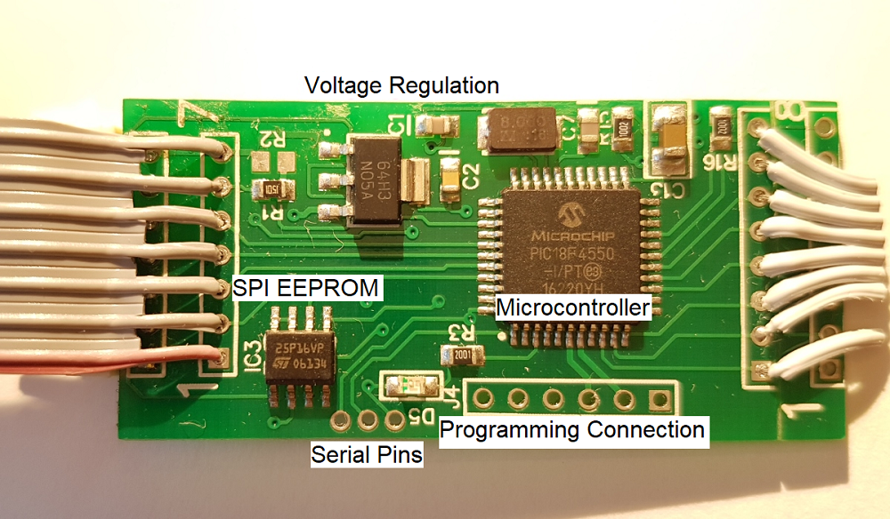
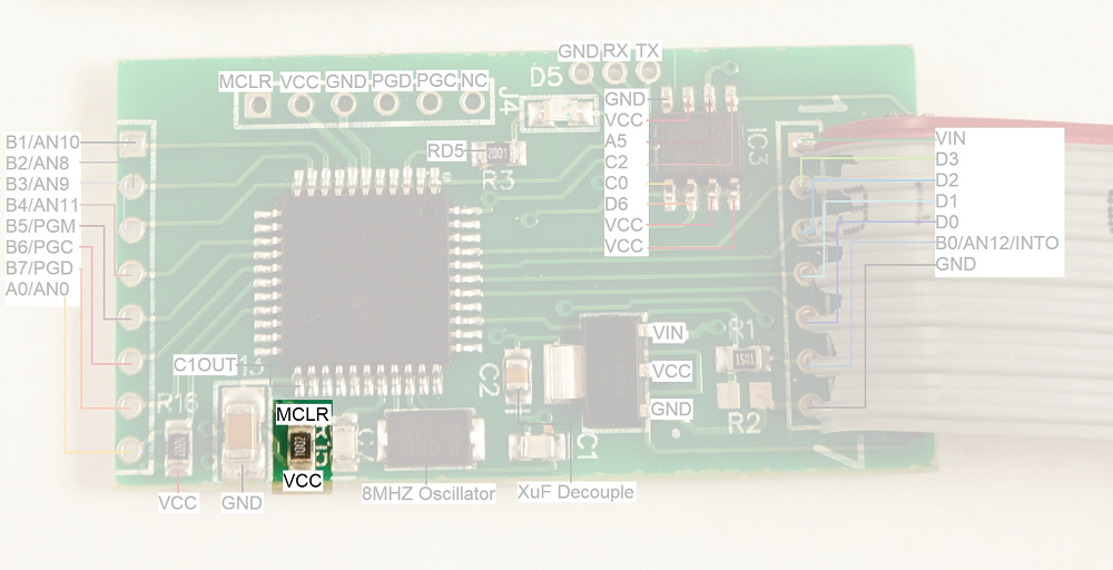
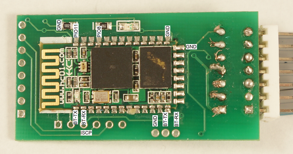
The front of the board is composed of a PIC18F4550 microcontroller, an M2P16 SPI EEPROM with 16Mbit flash memory, and a standard LM1117 3.3V regulator.
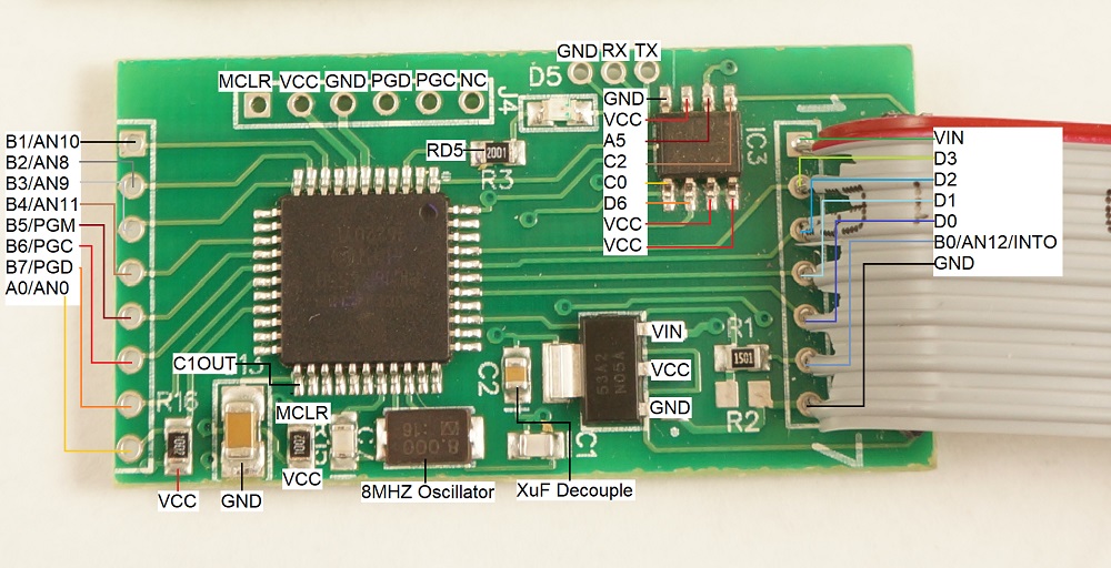
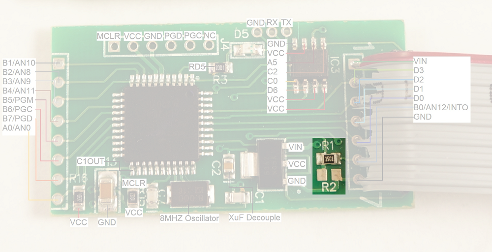
To get into some gritty details:
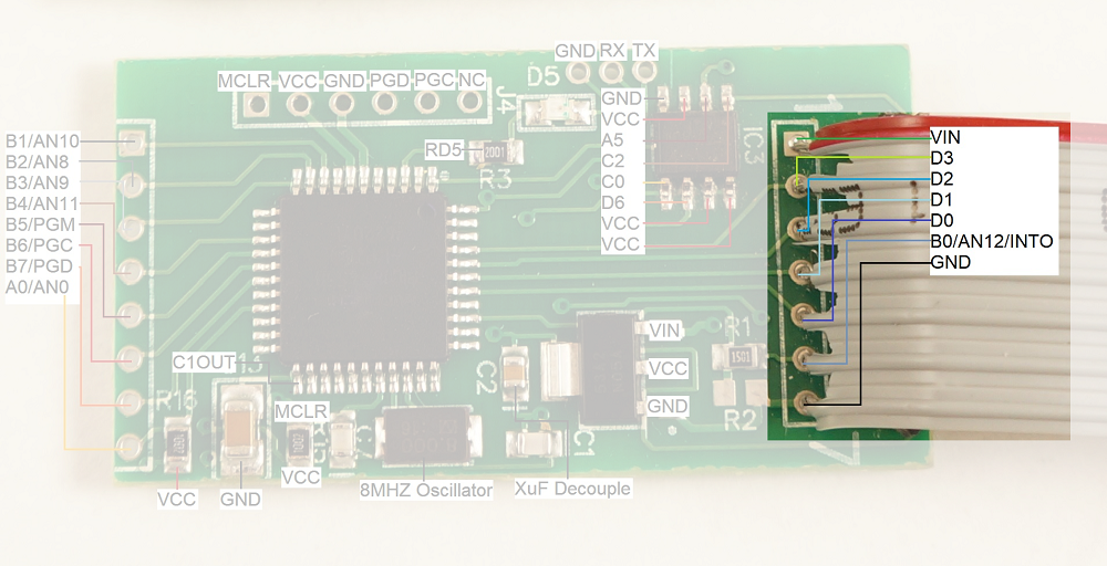
- R1 and R2 look to be a voltage divider when needed (R2 is not populated) to drop the voltage of the signals coming from the credit card reader. I presume the reader is outputting 12V signals and R1 (1.5K) is there to limit the current into the receiving pin, thus protecting the PIC from damage.
- There are three serial pins shown at the top of the picture. From left to right: GND, RX, TX. These seem to be an easy serial connection to the PIC. Perhaps used for bootloading new firmware. These pins connect to the Bluetooth module's RX and TX pins (respectively) and make it very easy to hook up a logic analyzer to sniff the serial traffic. (Thanks skimmer designer!)
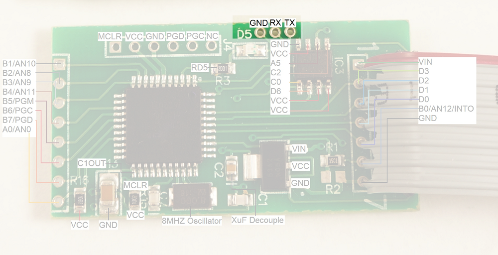
The voltage regulator is very common with a large package to (probably) withstand getting hot when given various input voltages (regulating 12V down to 3.3V can produce a bit of heat)
D5 is a status LED.
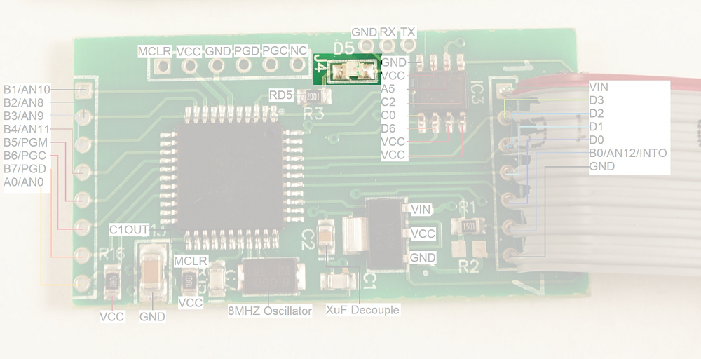
J4 is the super common PIC ICSP (in circuit serial programming) header. It's used to get firmware onto the PIC18F4550.
- C1 and C7 are loading caps to the 8MHz crystal. This makes sense as most PIC18F series can't run above 10MHz at 3.3V.
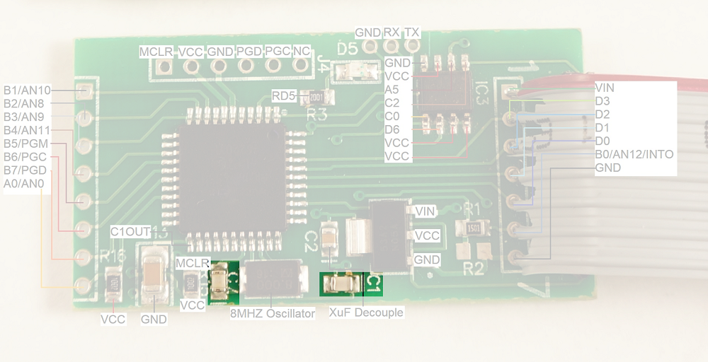
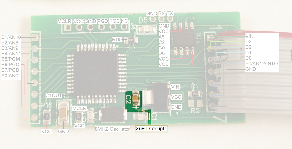
- C2 looks like a 0.1uF decoupling capacitor.
- R15 is a 10k pull-up on the reset (MCLR) line
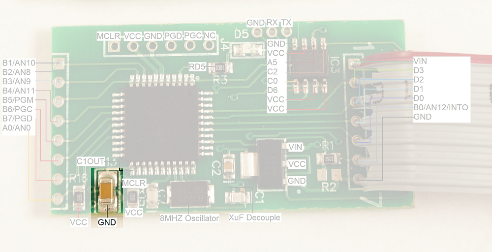
- C13 is a large cap on RA4/T0CKI/C1OUT/RCV. This could be a digital I/O, Timer0 external clock input, Comparator 1 output, or external USB transceiver RCV input. None of these have a clear reason to be connected to a large decoupling cap. This pin is not connected to any other part of the circuit.
The main connection to the credit card reader is via the connection labeled '1' through '7' shown on the right with a gray cable installed.
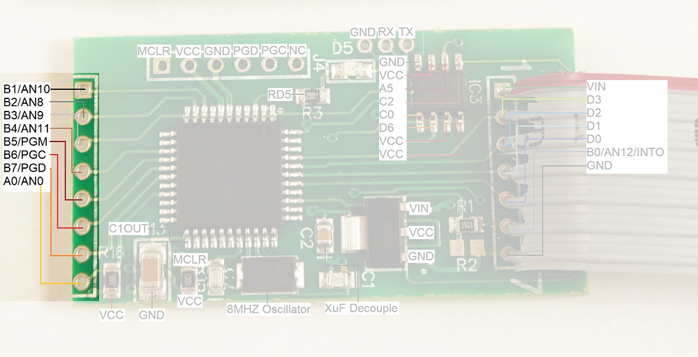
It is unclear what the second connector (shown on the left in the image above) is used for. This connection could be used for a variety of different things as the pins on the PIC that are broken out could be used as either inputs or outputs. My guess is that this is the connection to the keypad so that the skimmer can record pin numbers (for debit cards) when the pump has the right model or compatible keypad.
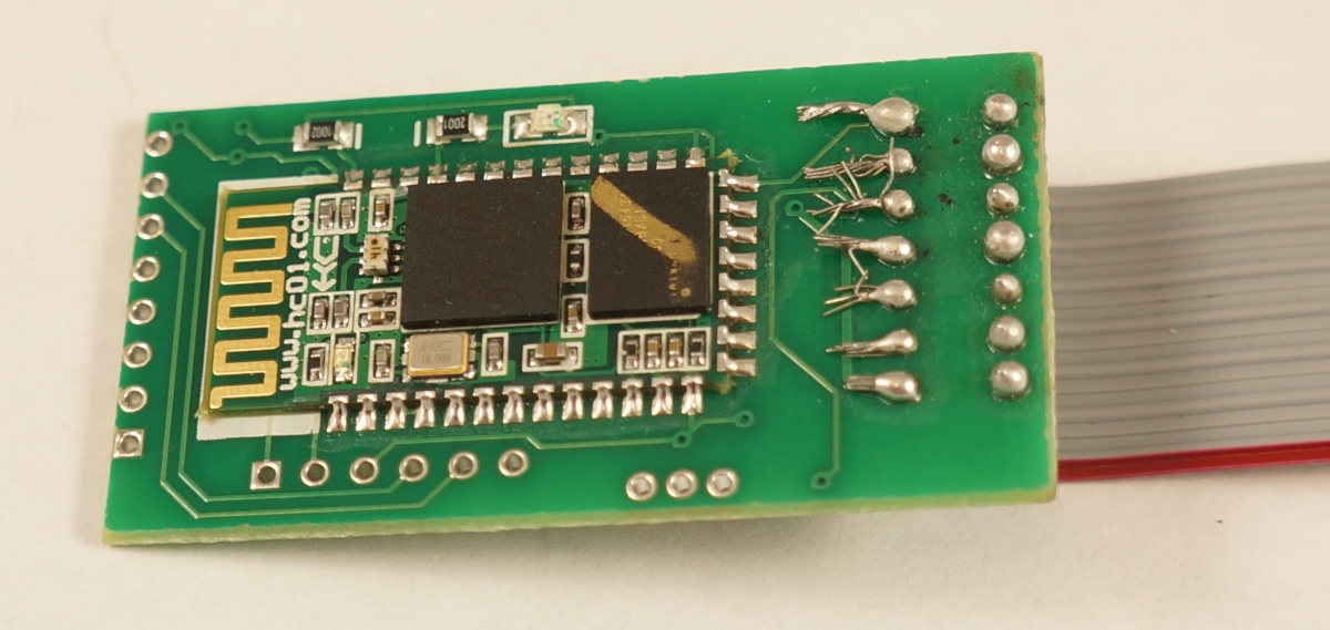
Rear of the Skimmer
These modules use an extremely common Bluetooth module called the HC-06. These are roughly $3 per unit and perhaps cheaper in quantity. Bluetooth has gotten shockingly cheap!
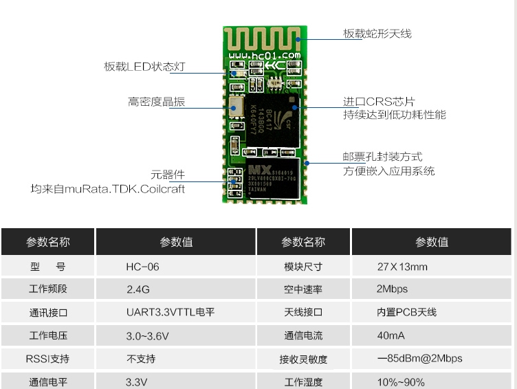
More on the Bluetooth module is below.
Build Quality
Interestingly, between the three units we were given we found three grades of assembly: excellent, good, and trash.
The main PCB assembly of the three units looks of reasonable to high quality. The front side of the skimmer (containing the PIC microcontroller) has been assembled with standard SMD practices using a solder paste, stencil, and reflow. It looks like it was mass produced from the quality of the fillets.
The Bluetooth module and various components on the back side look hand soldered but done by someone who knows how to use flux and how to solder well. The Bluetooth modules were most likely hand soldered to reduce the overall manufacturing costs (it basically costs double to stencil and reflow a 2nd side).
The cables and connectors were added by someone else, most likely the perpetrator. It’s really bad. On two units the stripping of the wire and solder is so poor that units will probably fail in the field because of shorting between pins.
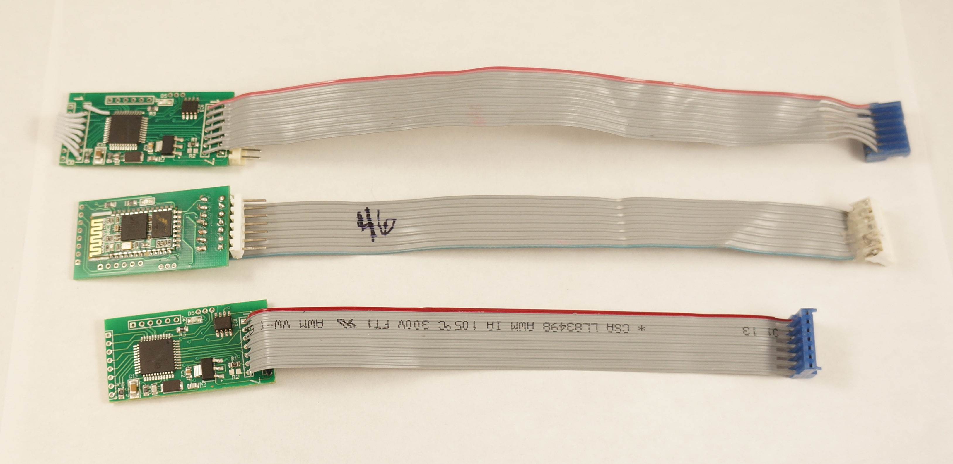
Two units have a 7 pin polarized connector with the tab cut off, possibly because they don’t know which way the pump controller will plug on. This is either very amateur (they guess when they plug in their unit which is pretty cavalier because it could fry their unit, the credit card reader, or both) or they’ve found that the connectors inside different pumps have different (opposite) orientations and they want to build a unit that can quickly work with either polarization. It’s unlikely the pump controller market would gravitate towards the same number of pins using the same type of connector but use two different orientations. So I’m guessing the builder of these units is not knowledgeable enough to figure out where pin 1 lives on the polarized connector and just resorts to guess and check: Plug it in, does it work? No? Switch it around the other way.