Gas Pump Skimmers
 Nate
Nate 
Characteristics of the Device
We powered the skimmer with 5V from USB. On powerup the main status LED blinks 3 times. The Bluetooth LED blinks fast at 4Hz when powered but not connected.
Connecting to the skimmer using Bluetooth on a computer is straightforward. We used the default password of 1234 and noticed the Bluetooth LED blinks on at 2Hz and then off for 2 seconds when connected.
On our setup COM-6 was the bluetooth SPP that became available once we were connected. Sending ? to the skimmer caused it to respond with 1 at 9600bps.
Known Commands
Here’s what we were able to glean from hammering the skimmer with various serial strings.
- Power the skimmer with 5V to 12V from the gray cable (or 3.3V into VCC)
- Connect to HC-06 with password 1234 using a laptop
- Open a terminal program at 9600bps
- ‘?’ is a good way to see if module is responding. (Numbers don’t do anything on their own.)
- Lower case letters do nothing
Identified Commands:
- ? - returns 1
- P - returns M
- D - Waits for 6 characters then stores them. Originally ‘123456’ and we thought it was the device ID or password. However, changing this setting does not seem to have an effect.
- C - Displays the 6 characters that are stored based on D
- @ - Look up memory location. Follow the @ with two more characters in binary form, returns credit card details stored in memory. For example, @[00][01] (shift+2, Ctrl+shift+2, Ctrl+a) returns the 2nd byte stored in EEPROM. See ascii table for info on how to send binary characters from keyboard combinations.
- % - waits for a character then does nothing
- E - causes serial to stop responding to serial commands. BT still open/connected. Power cycle device to get it back responding. This could possibly be used to deactivate a device in the field.
- ~ - Erase all SPI flash. This is how to erase all the credit card numbers. Unit blinks the status LED for ~20 seconds (EEPROM takes time to erase). The unit will buffer any incoming serial characters during the time it takes to erase the EEPROM (serial interrupts and buffer are being used).
A skimmed credit card record looks like this (we've altered the card number):
T1 %B374328830305879^YOU/A GIFT FOR            ^20042221330999242?
T2 ;374328830305879=200912211090924100000?
This looks like a direct copy of the serial we would expect out of a serial card reader. T1 indicates track 1 data, T2 for track 2, etc. The records are stored on EEPROM in clear text (remember, make it idiot proof for the user). It looks like someone used a gift card to buy gas. Note that this record is 113 characters. Let's say a record is 256 bytes. With 16Mbit of flash storage that's 2MB or approximately 7,800 credit card records that could be stored on a device. (Yikes.)
On the units we were given we found on average 24 records per device. This seems low. I'm not sure where these devices were located but one would expect at least 24 credit card users per day. This may indicate the perpetrator was regularly visiting the pumps and harvesting the records on a daily basis.
Getting Data Off Skimmer
We are not going to provide an example app that pulls data from the device. If you're savvy enough to build an app from the information provided in this tutorial you are likely to earn more money using your mad skills for good rather than evil.
If you're a law enforcement official you should have physical access to the device. There are a few methods to get the data from the EEPROM.
First, you'll need an EEPROM reader. We like using a cheap SPI programmer from Amazon. The software for Windows is a bit hard to locate. We had the best luck with version 1.29 from Tosiek Zanakow’s website. We have hosted a copy of the software here as well. Use at your own risk.
Next you'll need to connect the Programmer to the EEPROM. There are two methods: Using a SOIC clip or hot-air removing the EEPROM. The SOIC clip is the least destructive method but requires dexterity and patience. Hot-air rework is more reliable but requires removing the IC from the board and may create evidence provenance issues.
SOIC Clip Method
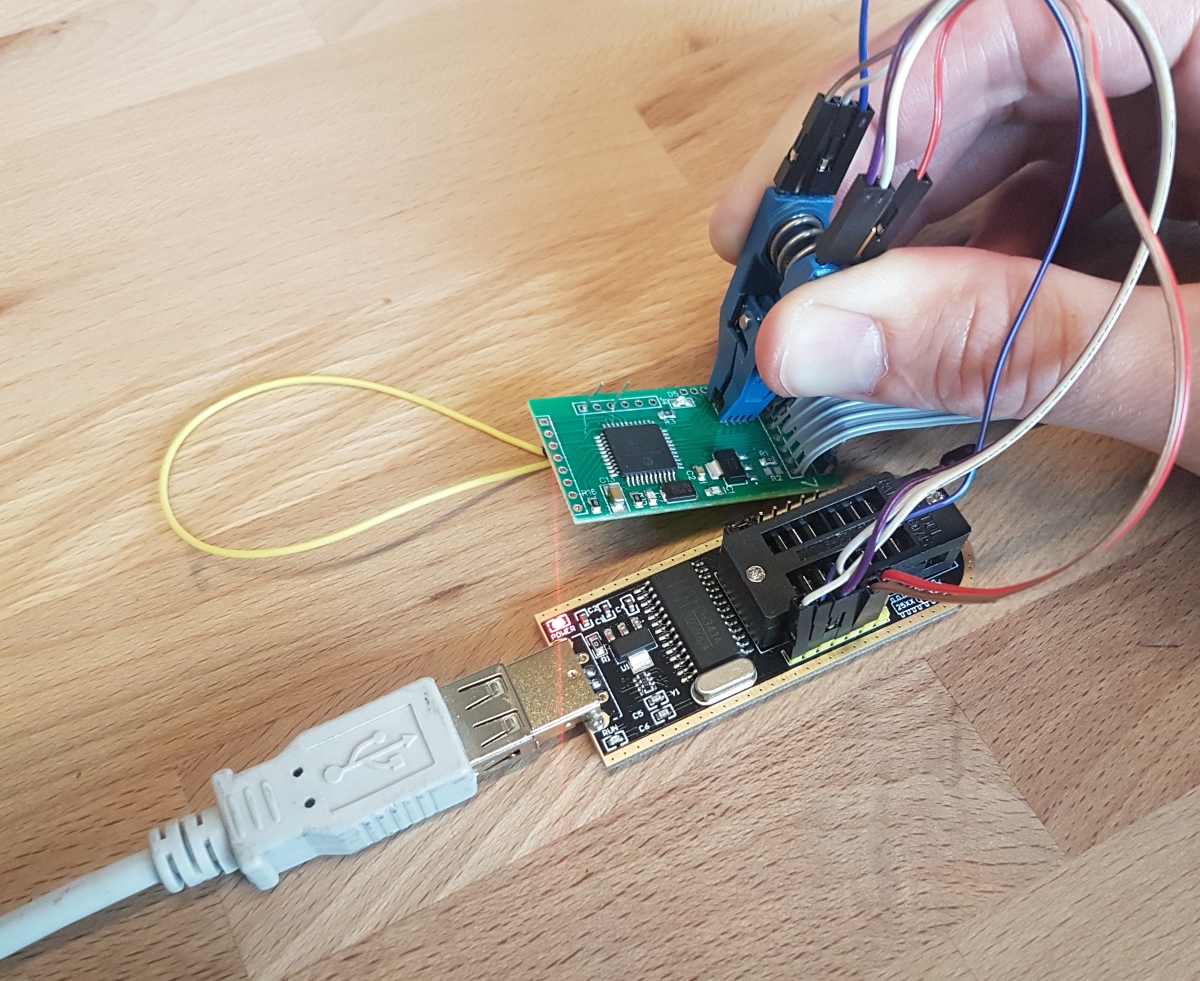
We use a SOIC Test Clip to make a temporary electrical connection to the SPI EEPROM. 12" Female to Female jumper wires connect the SOIC Clip to the EEPROM Reader. The female jumper wires connect nicely with the 6 SPI pins on the CH341A EEPROM Programmer. Only 6 wires are needed; the write protect and hold pins can be left floating. We selected the ES25P16 from within the software to read the IC over SPI.
The last thing you need to do is to put the PIC18F4550 into reset. This is because the CH341A will provide power to the skimmer. Once power is applied the PIC will boot up and attempt to connect with the EEPROM. If you're trying to read the EEPROM through the clip at the same time you'll have bus contention. This is bad and will prevent the programmer from correctly reading the EEPROM.
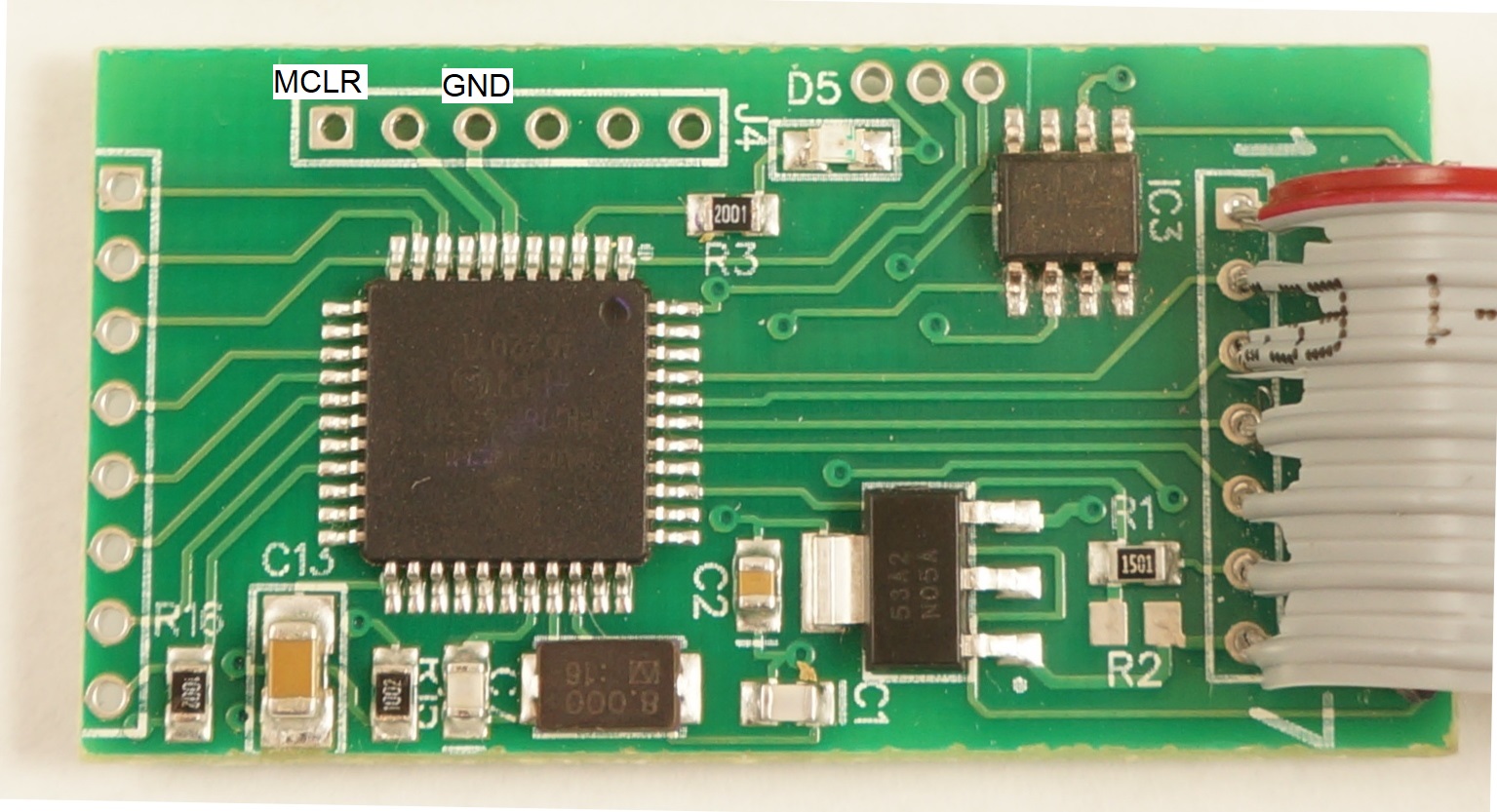
To get the PIC into reset you'll need to either hold or solder a wire from MCLR to GND. This will cause the PIC to stay in reset and allow you to read the EEPROM to a binary file from the CH341A software. Renaming this binary file to a .txt extension will make the information viewable in a normal text editor.
The problem with this method is that the SOIC clip is difficult to keep in place. Things like to move causing the clip to slip off the EEPROM. The connections are not great but with a little practice it can be made to work.
Hot-Air Removal
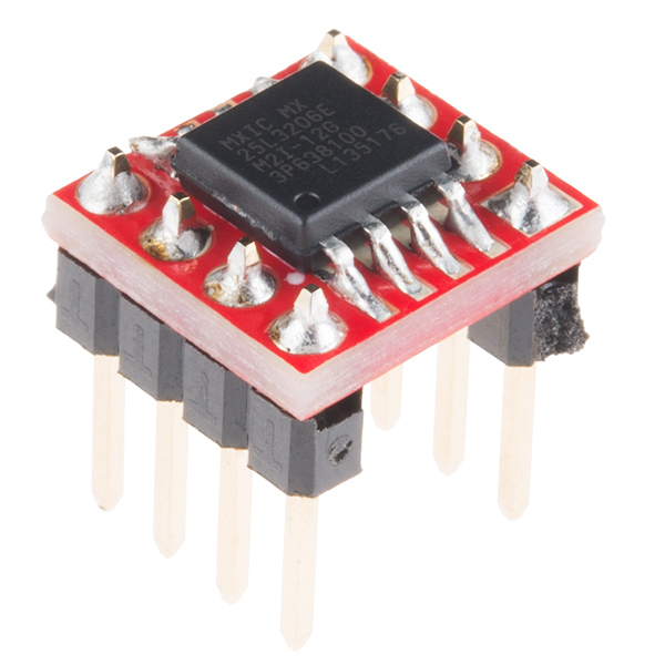
The alternative method is to use hot-air to remove the EEPROM from the skimmer and then solder it to a SOIC breakout board. Solder male headers to this breakout board and you will be able to make solid connections from the EEPROM to the EEPROM Programmer and read the contents. You will not need to hold the PIC in reset for this method to work (because the PIC is no longer connected to the EEPROM).