FTDI SmartBasic Hookup Guide
 SFUptownMaker
Hardware Tour
The FTDI SmartBasic hardware is pretty simple. It routes the serial signals from an Arduino Pro, Pro Mini, Fio, or LilyPad board (along with any other board which uses the standard FTDI header footprint) either to the programming PC via a USB-to-serial bridge or to any other device with the FTDI Basic-type header. It uses the venerable FT232RL chip used on the original FTDI Basic boards and the TS3USB221A signal multiplexer from TI to make connecting to multiple serial devices easy.
The Board
The actual board design is fairly compact. We've left the headers off, so you can choose the header most appropriate for your application.
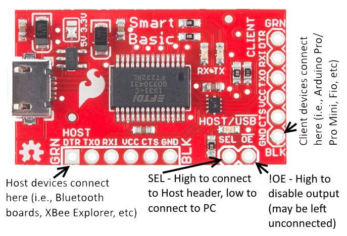
The header labeled "CLIENT" is basically the same as the output header on a standard FTDI Basic board. If you connect that header to the Arduino as you would with a normal Basic, you can program the Arduino exactly as you would normally, and never notice a difference.
The benefit comes in with the "HOST" header. That header can be connected to any host-type device (such as another FTDI board, or any of our Bluetooth Mate type boards). You can then wire the !OE and SEL lines to pins on the Arduino to enable the application code to route serial data from the hardware port to either the USB serial bridge or the device connected to the HOST header.
Because of the pull-down resistor on the SEL line, if that pin is left floating, the default destination for the traffic is the USB serial bridge. When in bootloader mode, all non-serial pins will be high impedance inputs, so after the Arduino IDE resets the Arduino board the bootloader and the PC will be able to communicate until the application loaded changes the level of that pin.
The AUX/!USB LED will be lit when the HOST port is selected and off when the data is being routed to the USB serial bridge. There is a solder jumper which can be adjusted to change the voltage on the VCC pins on the two headers (and the IO voltage on the FT232RL chip) from 3.3V to 5V; if that jumper is cleared completely, a supply on one of the two serial headers can be used to power both devices and the VDDIO, should you need a voltage other than 5V or 3.3V.