FTDI SmartBasic Hookup Guide
 SFUptownMaker
Connecting the SmartBasic
One of the common problems encountered when developing with a serial-connected Bluetooth dongle is the inadequacy of the Arduino SoftwareSerial library. Transmissions with software serial are resource intensive, blocking the processor for the duration of the transmission. Long receives easily overrun the buffer, and can throw off the internal clocks used for millis() and micros().
Obviously, it's desirable to use the hardware serial port, if possible, as it bypasses most of these issues. However, connecting anything other than an FTDI-type serial port to the hardware serial port header prevents it being used for loading code unless the other device is removed. Here's a diagram showing how to connect the FTDI SmartBasic in a way that removes that problem.
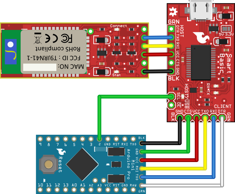
You can see that the connections from the Bluetooth Mate and the Arduino Pro Mini are straight-through; no need to cross wires, so you can plug them right in. Also note the connection of digital I/O pin 2 to the SEL line on the FTDI basic. This is what allows the multiplexing of the serial data: when the board is in bootloader mode, that pin will be a digital input and the SEL line will be pulled low by a pull down resistor on the SmartBasic. That will route the data to the FTDI chip to be sent to the PC, and data from the FTDI chip will be routed to the Pro Mini board, and bootloading of a sketch can occur normally.
Note, as well, that the CTS and DTR pins between the SmartBasic and the Bluetooth Mate are not connected. Since the multiplexer on the SmartBasic only has two channels, only the data channels can be swapped. That's important, though, because DTR is needed to reset the Arduino at bootload time. If it were being re-routed, that would defeat the purpose of this board.
After the application sketch has loaded, the user can switch between the two data endpoints (the PC and the Bluetooth Mate) by asserting pin 2 high (for the Bluetooth Mate) or low (for the PC). Here's a simple Arduino sketch showing that in action.
#define SEL 2  // When the SEL pin is held low, the data will be
               //  routed to the PC via the USB-serial bridge.
               //  That port is also the port used for programming
               //  by the Arduino IDE. When in bootloading mode, a
               //  pull-down resistor on the SmartBasic causes it
               //  to remain in programming mode.

#define ARDUINO_IDE   LOW  // Constants to make our routing change
#define AUX_TERMINAL  HIGH //  more obvious. When the SEL pin is
                           //  LOW, data is routed to the
                           //  programming port.

void setup()
{
  Serial.begin(115200);    // Set up the hardware serial port.

  pinMode(SEL, OUTPUT);    // Make the select line an output...
  digitalWrite(SEL, ARDUINO_IDE); // ...and connect the board to
                           //  the Arduino IDE's terminal.
}

void loop()
{
  // The loop just says "Hello" to the two terminals, over and
  //  over, forever. Note the use of the "flush()" function. If
  //  omitted, the Arduino will re-route the serial data before
  //  the transmission has been completed; flush() causes the
  //  Arduino to block until the serial data output buffer is
  //  empty. Failure to use flush() will result in data being
  //  sent to the wrong device, or to multiplexer changes during
  //  transmission which may cause framing errors or data
  //  corruption. *Always put in a flush() before you change
  //  destination devices or disable the output.*
  Serial.flush();
  digitalWrite(SEL, ARDUINO_IDE);
  Serial.println("Hello, Arduino IDE!");

  // Swap to the non-Arduino terminal and say hello.
  Serial.flush();
  digitalWrite(SEL, AUX_TERMINAL);
  Serial.println("Hello, auxilliary terminal!");

  Serial.flush();

  delay(500); // This is a rate-limiter only. The temptation to use
              //  delay() instead of flush() is strong, but fight it.
              //  If you use delay, you will *certainly* make a change
              //  to the code which makes the original delay time too
              //  short for the new serial data stream, resulting in
              //  data corruption. flush() will *always* be the right
              //  length.
}
Finally, I've omitted discussion of the OE pin. It can be left unconnected during normal use; however, if for some reason it becomes useful to disconnect the TX and RX pins on the SmartBasic from the client board, that pin can be asserted HIGH, which will put the client-side pins on the multiplexer into a high-impedance mode.