FreeSoC2 Hookup Guide V14
 SFUptownMaker
 Introduction
The FreeSoc2 is SparkFun's PSoC5LP development board features a full onboard debugger, support for 5V and 3.3V IO voltages, and a CY8C5888AXI-LP096 processor with 256kB of flash, 64kB of SRAM and 2kB of EEPROM. The onboard oscillator can drive the processor at up to 80MHz, and the Cortex-M3 core provides superior performance.
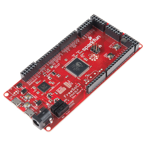
FreeSoC2 Development Board - PSoC5LP
DEV-13714The real power of the PSoC5LP isn't in the processor, however. Wrapped around the processor is a rich analog and digital programmable fabric, which can be configured to provide many functions that would otherwise need to be realized in code (lowering system performance) or external circuitry (adding cost and board size). In addition, the highly flexible fabric means that most any function can be routed to most any pin, which makes this a wonderful tool for development and allows board layout errors to be solved, at least temporarily, pretty easily. Conceptually, this fabric is similar to an FPGA or CPLD.
Covered in This Tutorial
We're going to discuss two different ways to tap the power of the PSoC. We've ported the Arduino core to the PSoC5LP, so you can write code for the board in the standard Arduino IDE. The board duplicates the functionality of an Arduino Uno R3's various hardware peripherals on the pins, so many examples, libraries, and shields will work out of the box.
The drawback of using the Arduino IDE, however, is that it lacks any means of configuring the programmable fabric (at the moment, at least). To get the most out of the device, you'll need to use the PSoC Creator IDE, which is free of charge with no code limits from Cypress Semiconductor. Sadly, the PSoC Creator software is Windows-only at this time. If you want to see that change, consider piping up on the Cypress forums!
In this tutorial, we're going to go over the detailed specifications and layout of the board, how to add support for the board to the Arduino IDE, and how to get started with a simple blink project on the PSoC Creator IDE.
Required Materials
We're going to keep it simple; the FreeSoC2 has an onboard LED and user-accessible pushbutton. We'll use those for our lessons. That means you'll only need the FreeSoC2 board and a micro-B USB cable. You may, however, find it useful to have a second USB cable, as that will allow you to connect to both the debugger and the target at the same time.
Suggested Reading
If you're unfamiliar with the Arduino IDE, but want to learn, check out our tutorial on installing the Arduino IDE.
As with any development platform, it's always wise to read the datasheet. Check out the datasheet for the PSoC5LP CY8C58LP before continuing.
Hardware Overview
There's a lot going on on this board: two processors, two USB ports, a ton of headers, and all sorts of configurable options.
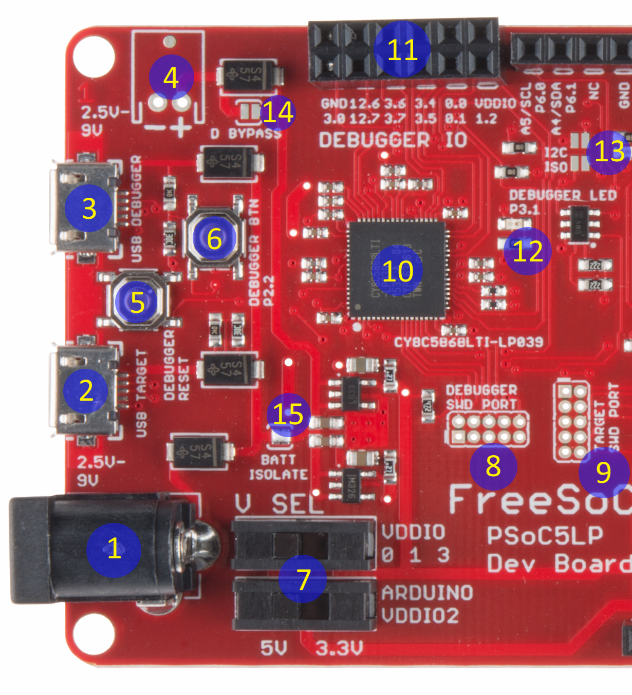
We'll take a hardware tour, one element at a time, starting with the debugging and connection elements on the left.
- 5.5mm x 2.1mm center positive barrel jack -- This fits all of SparkFun's standard "wall wart" type power supplies. While the regulators on the FreeSoC2 can handle input voltages up to 12V, it's best to keep the input voltage as close to 5V as possible.
- "Target" USB Port -- Provides USB connectivity to the target processor (the CY8C5888). When uploading code via the Arduino IDE, you'll connect to this port.
- "Debugger" USB Port -- Connects to the debugger IC. Connecting to this port also creates a USB serial port that can be used to get and send data from and to a UART on the target processor.
- 2.5mm JST PH series connector footprint -- Our through hole 2-pin JST PH connector fits here, allowing you to power the board with any of our standard lithium ion polymer batteries.
- Debugger reset button -- Resets the debugger. You will probably never need to use this.
- Debugger user button -- Can be used to provide input to the debugger IC; currently unused.
- IO voltage selection switches -- These switches allow you to select the voltage of the I/O signals, either 3.3V or 5V, on the target processor. The PSoC5LP has four I/O voltage quadrants; the bottom switch allows you to select the voltage of the quadrant providing the Arduino header signals, and the top switch controls all the others.
- Debugger IC JTAG/SWD header -- This 2x5 0.050" pitch header can be used to program and debug the debugger itself. It's intended to support a connection to the MiniProg3 programmer/debugger from Cypress. You'll probably never need to use it.
- Target IC JTAG/SWD header -- Similar in nature to the header for the debugger; the signals on these pins also come from the debugger IC.
- Debugger IC -- The debug IC is also a PSoC5LP- in this case, CY8C5868LTI-LP039. The firmware it comes preloaded with (referred to as "KitProg") is freely available for download and modification; the part is bootloadable to replace the firmware or update it as new firmware becomes available.
- Debugger IC IO header -- There are a number of signals available on this header; they are not used by default but you may implement additional debugging features on the debugger IC that do use them.
- Debugger IC user LED -- Will be lit if the debugger can't detect a host, and will flash during data transfer (i.e., programming or debugging).
- I2C isolation jumpers -- These normally open solder jumpers allow you to connect the I2C lines on the target board with the debugger. Using Cypress's KitProg debugging software, you can snoop the I2C data traffic from the target IC. Normally, these are open, disabling this capability. Close them with solder blobs to connect the debugger to the target's I2C bus.
Battery Supply Diode Bypass -- If you populate the 2.5mm JST connector and run the FreeSoC2 off of a LiPo battery, you may find the ~0.5V drop across the diode which ORs the battery supply into the main supply rail. This jumper may be closed with a blob of solder to bypass that diode.
Caution: if you close this jumper but fail to open the "BATT ISOLATE" jumper (item 15), plugging the board into USB power may cause damage to your battery or even a fire as the 5V USB supply shorts to the LiPo battery output.Battery Isolate jumper -- Whenever you close the "D BYPASS" jumper (item 14), this jumper must be opened, to avoid risk of damage to the battery or fire.
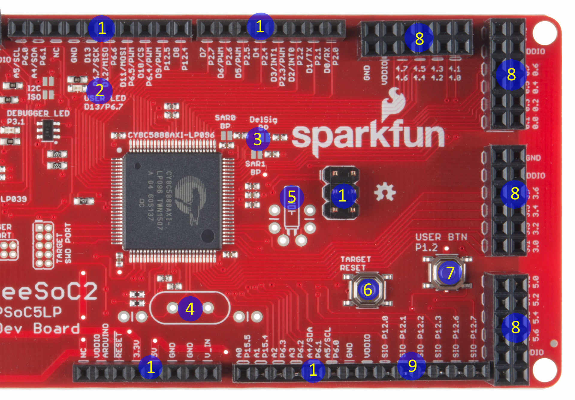
The right half of the board contains the target IC (a CY8C5888AXI-LP096) and the associated headers.
- Arduino Uno R3-type headers -- For the most part, these headers are completely compatible with the Uno R3 board. The only exception is the VREF pin, normally located between the I2C pins and the ground above D13, is no-connect for this board.
- Target user LED -- Tied to port 6, pin 7, which corresponds to D13 on the Arduino mapped headers.
- ADC reference bypass capacitor jumpers -- These jumpers allow you to add a 100nF capacitor to three of the PSoC part's pins, to provide a bypass for ADC voltage references to increase the reference's accuracy.
- High-frequency crystal footprint -- if you need better accuracy than can be achieved by the onboard oscillator, you may add a standard HC/49 crystal here.
- Low-frequency crystal fooprint -- if you want to implement an RTC, you may add a 32.768kHz clock crystal here.
- Target IC reset button -- This button resets only the target IC.
- Target IC user button -- This button can be mapped to any purpose within the application; the button pulls down to ground and is not tied to any other header.
- Additional IO headers -- These 2x6 headers are all additional I/O, and their voltage level (along with the voltage present on the VDDIO pins of those headers) is controlled by the top VDDIO set switch on the left end of the board and can be set to either 3.3V or 5V.
- SIO pins -- These six pins are special in that they can be connected to a signal voltage that is higher than their nominal I/O voltage. They can, of course, be used normally as well. This allows these pins to be 5V tolerant when the rest of the IO pins are running at 3.3V.
Using the Arduino IDE
Adding Support for the FreeSoC2 to the Arduino IDE
Currently, the only way to add the FreeSoC2 support to the Arduino IDE is to download the files directly and manually install them. Instructions on how to do so are below. The first step is to use the Board Manager to add support for the ARM processor core.
Adding ARM processor support
Unlike "true" Arduino boards like the Uno or Leonardo, the PSoC5LP uses an ARM Cortex-M3 processor core. Late model boards, such as the Due and the Zero, also use ARM processors, so the Arduino team have added the ARM-GCC toolset to the officially supported toolchain. That's good for us, because it means we don't have to do much work (at least, on the toolchain) to add support for the PSoC.
All you need to do is open the Arduino IDE, and launch the board manager (see image below).
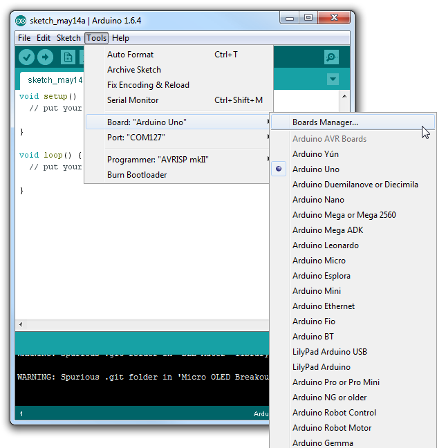
One of the by-default available options is "Arduino SAM Boards"; these are boards using the ARM Cortex processor (specifically, the Atmega SAM parts). Simply click in that box to highlight it, and click "Install".
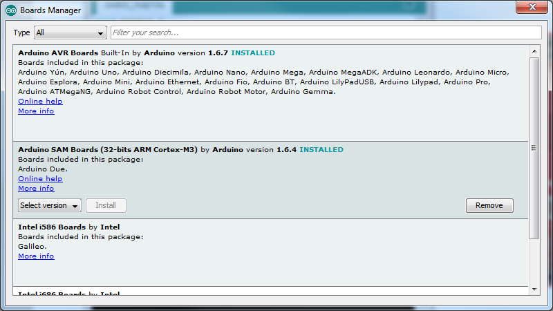
Once the install is complete, you'll see a new subgroup in the boards menu for the Arduino ARM boards. Now, it's time to add support for the PSoC.
Adding Support for PSoC Boards
Manually adding support
To add support manually, you'll need to download the files from the GitHub repository.
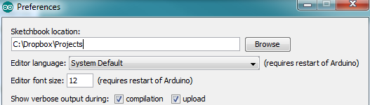
Once you've got your copy downloaded, all you need to do is copy the "Hardware" directory into either your sketchbook (you can find your sketchbook path in the preferences window, in Arduino) or into the main install directory for the Arduino IDE. Either way, if there's an existing "Hardware" directory. The files should just install alongside the existing files.
The other files in the folder are the PSoC Creator IDE project files for the implementation of the Arduino hardware and core software. Once you're comfortable with using the FreeSoC2 in the Arduino IDE, you may wish to open this up as a first step towards using the full features of the part.
If there isn't a "Hardware" directory in the sketchbook, that's fine. Just drag the "Hardware" directory from the zip archive into the sketchbook.
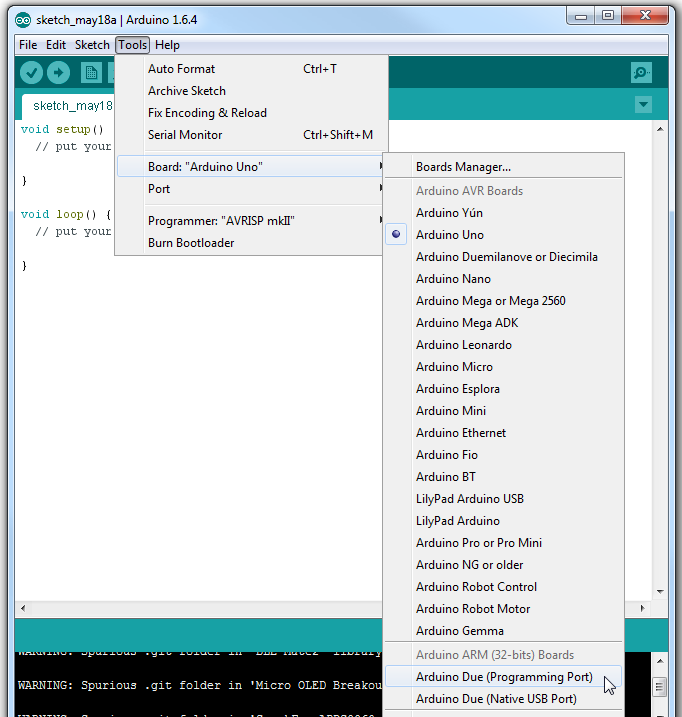
Restart the Arduino IDE, and you should see the boards in the "Boards" menu.
Programming the FreeSoC2 Board With an Arduino Bootloader
If you've purchased an early version of the FreeSoC2 (V11 or earlier; look on the back of the board, under the power connector for the version number), or if you've previously used the PSoC Creator software to develop on your FreeSoC2 board, you'll find that it will not respond to the bootloading commands of the Arduino IDE.
You'll need a Windows computer (at the moment; we're working on a Mac/Linux solution for the near future) to program the part with the bootloader hex file.
Once you've installed the software, follow these instructions:
- Plug the board into your computer, and connecting via the "Debugger" port (item 3 on the left-half hardware tour picture). Do not connect to the "Target" port at this time.
- The drivers for the KitBridge programmer/debugger (onboard the FreeSoC2) have already been installed as part of the Programmer installation. If Windows fails to detect them automatically, they can be found in the Programmer installation directory. If you have Windows 8 you may want to check out this tutorial about installing unsigned drivers.
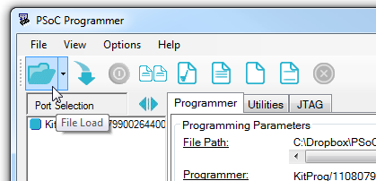
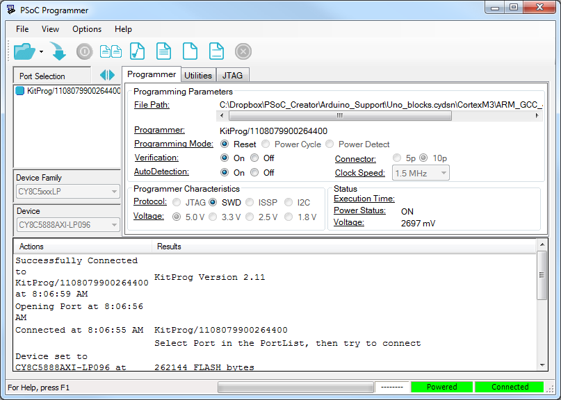
Launch the Programmer. You'll see this window:
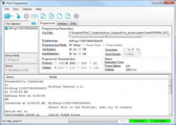
Load the "Bootloader.hex" file, located in the support package you downloaded above ("Hardware/SparkFun/psoc").
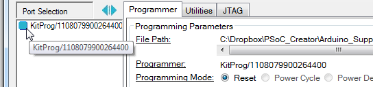
Click the "KitProg" entry to select the board for programming. If there is no "KitProg" entry in the menu, check to make sure the driver has finished installing. If you aren't able to select the KitProg, check to make sure there isn't another copy of Programmer (or PSoC Creator, perhaps) running in another window.
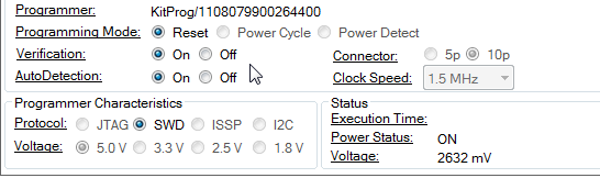
Select "On" for both "Verification" and "AutoDetection".
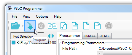
Click the "Program" button to load the bootloader onto the board.
Connect the "Target" USB port on the board. The driver can be found in the support package you downloaded above ("Hardware/SparkFun/psoc").
If all has gone well, you'll have a new com port (named "Cypress USB UART"), and, if you open the serial monitor in the Arduino IDE and send "H" and "L", you should see the LED on the board toggle.
Writing Code in Arduino
Differences Between FreeSoC2 and Other Arduino Boards
The core support for the PSoC is made to closely resemble the Arduino Uno R3, and by and large, code which runs on the Uno R3 will work on the FreeSoC2 with little or no change. Here are some of the differences to be aware of:
- The hardware serial port on pins 0 and 1 is
Serial1, rather thanSerial, as on the Arduino Leonardo. Serial prints to the computer, via the USB port. - The AREF pin is not connected on the FreeSoC2.
- random() returns a 24-bit value instead of a 32-bit value.
- Some of the more advanced string manipulation is, as yet, unimplemented.
- Pin numbers should be defined as
longrather thanint.
We've ported the most core libraries to the FreeSoC: SPI, Wire (I2C), and Servo, and we've created a driver library for the WS281x programmable RGB LEDs. Other native Arduino libraries may or may not work. Here's a list of libraries we've verified with the FreeSoC2 in Arduino:
Extra Serial Port
As mentioned above, all Serial commands go through the USB connection the target maintains with the PC. This is awkward, though, because it means that text sent immediately after reset will often be missed in the time between the code beginning to run and the user opening the terminal window.
There's an option for the FreeSoC2, however: when the Debugger USB port is connected to the PC, it will enumerate as, among other things, another serial port. That port can be used to send and receive data from the Arduino application via the Serial1 interface. We'll demonstrate that below.
Example
This example will show you how to access pins not in the normal Arduino range, as well as using the serial ports.
Remember to select the "PSoC Dev Board" in the boards menu!
language:c
/******************************************************************************
Example.ino

Simple example demonstrating the use of Serial ports and extra pins on the
FreeSoC2 board within the Arduino IDE.

14 May 2015

Developed/Tested with:
FreeSoC2
Arduino.cc IDE 1.6.4
This code is beerware; if you see me (or any other SparkFun employee) at the
local, and you've found our code helpful, please buy us a round!

Distributed as-is; no warranty is given.
******************************************************************************/
// Note the use of long here instead of int! This is important.
const long LEDPin = 13; // As on most Arduino compatible boards, there's an LED
                       //  tied to pin 13. pinMode() works the same with the
                       //  FreeSoC2 as it does normally.
const long buttonPin = P1_D2; // Pins can also be referred to by port number
                       //  and pin number. These numbers are given on the board
                       //  as P<port>.<pin>. P1_D2 is connected to the user
                       //  button on one side ang ground on the other.

void setup()
{
  // pinMode() functions are unchanged.
  pinMode(LEDPin, OUTPUT);
  // The onboard user button needs to be a pullup-enabled input.
  pinMode(buttonPin, INPUT_PULLUP);
  Serial.begin(9600);  // This is the same as it is on the Arduino Leonardo.
                       //  It represents the logical serial port connection to
                       //  the PC.
  Serial1.begin(9600); // Again, same as the Leonardo. This port is the physical
                       //  IO pins (0 and 1) on the headers. It can be accessed
                       //  via the KitProg serial port which is available when
                       //  the Debugger port is connected.
}

void loop()
{
  // digitalRead() is unchanged.
  int pinDown = digitalRead(buttonPin);

  // Check for button pressed...
  if (pinDown == LOW)
  {
    Serial1.println("KitProg! Button pressed!");
    Serial.println("USB! Button pressed!");
    digitalWrite(LEDPin, HIGH);
  }
  else
  {
    digitalWrite(LEDPin, LOW);
  }

  delay(250);
}
Getting Started with PSoC Creator
If you want to move beyond the basics, you'll need to install Cypress's PSoC Creator IDE. It's free, with no code size limitations, although Cypress does ask that you register before downloading.
It is, sadly, Windows only.
We'll go through a very simple project here, just a step more involved than a normal "blink" example.
Connecting the Board
For programming and debugging within PSoC Creator, you'll need to connect the board via the "Debugger" USB port. The driver should have been installed as a part of the Creator install process. If not, you can find them in the Creator installation directory. If you find driver installation problematic under Windows 8, we have a tutorial to help with that.
There's no need to connect the "Target" port, unless you are actually creating a project that uses USB, which is beyond the scope of this tutorial.
Creating a Project
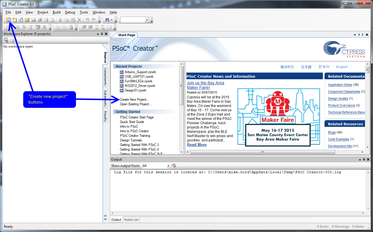
This is what you'll see when you launch Creator. To start a new project, you can either click the "Create New Project..." link on the Start Page, the "New" button in the menu bar, or open the "File" menu and choose "Project..." in the "New" submenu.
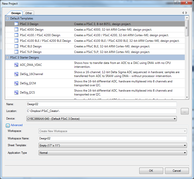
That will open this window. I've clicked the '+' next to "Advanced" to show more choices.
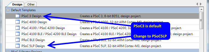
The first thing to do is to select "PSoC 5LP Design" from the "Default Templates" list. This will set up some things for you, including setting compiler options and paths.
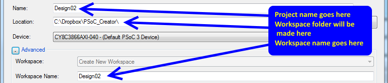
The "Name" field is the name of the project. PSoC Creator organizes applications into workspaces which contain one or more projects. For instance, you may wish to have an application and its bootloader as part of one workspace, to keep them related.
Down below that "Advanced" fold you'll see a couple of more options related to project and workspace management. If you currently have a workspace open, you have the option (via the "Workspace" drop-down) of electing to add this project to that workspace. Otherwise, it will be greyed out and you'll need to provide a workspace name.
The IDE will create a new directory with the workspace name in the directory specified in the "Location:" field; it will create a subdirectory in that directory with the name of the project (as declared in the "Project:" field).
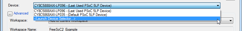
In the "Device" menu you'll find an option to launch the device selector.
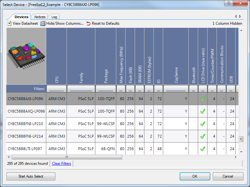
This pulls up a list of all the various PSoC5LP parts. Find the CY8C5888AXI-LP096, highlight the line, and click okay. You'll probably never need to change this again; The Creator remembers the parts you've used in the past.
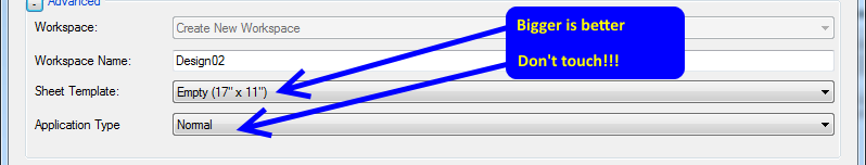
"Sheet template" is the size and format of the schematic capture sheet you'll use to define the hardware components of your design. I've selected 11"x17" ledger size, and that's a good place to start until you've gotten accustomed to breaking projects up into smaller chunks and making components in libraries.
Finally, you have the option to select whether your application is a bootloader, is bootloadable, or is a multi-app bootloader (to provide fail-safe operation). We'll leave that at "Normal" for now.
Click "OK" to move to the next step.
Adding Hardware
Before you can go any further, you'll need to add some sort of hardware to the schematic. As you add hardware elements to the schematic, the IDE will generate API files to support the hardware.
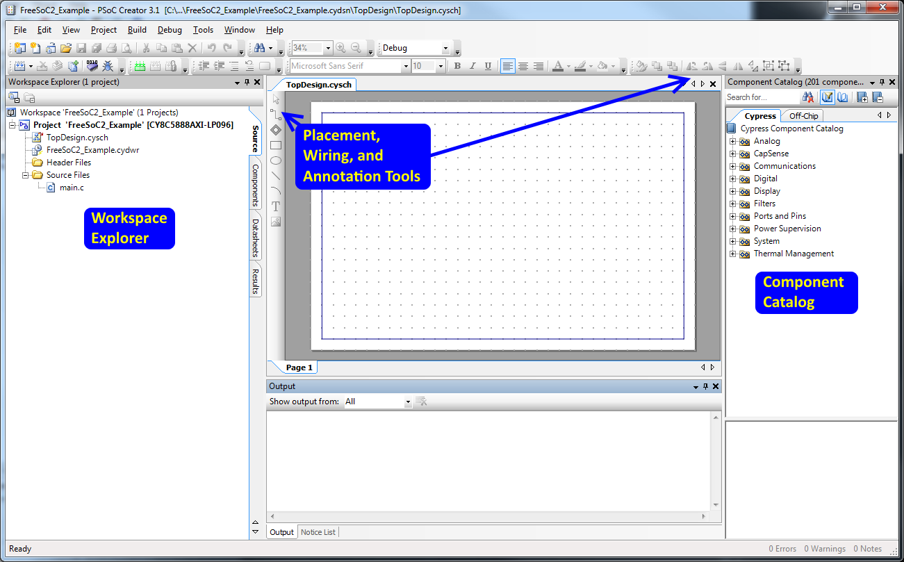
On the right side of the screen, you can see a tree-structure frame called the "Component Catalog". These are all the various hardware devices you can have the IDE build out of the chip's resources. The "Cypress" tab contains active devices, which will actually be created, and the "Off-Chip" tab allows you to add things like switches and LEDs. Take a moment to review the available components. There's a lot of really good stuff in there, that would normally either require off-chip resources or a great deal of resource-hogging code to implement.
On the left is the "Workspace Explorer", a tree view of the files included in the projects included in this workspace. The active workspace (i.e., the one that builds/programs when you just click the "Build" button in the shortcut bar) is bolded. Note that, although there are "folders" in this listing, those folders have nothing to do with the actual location of the files!
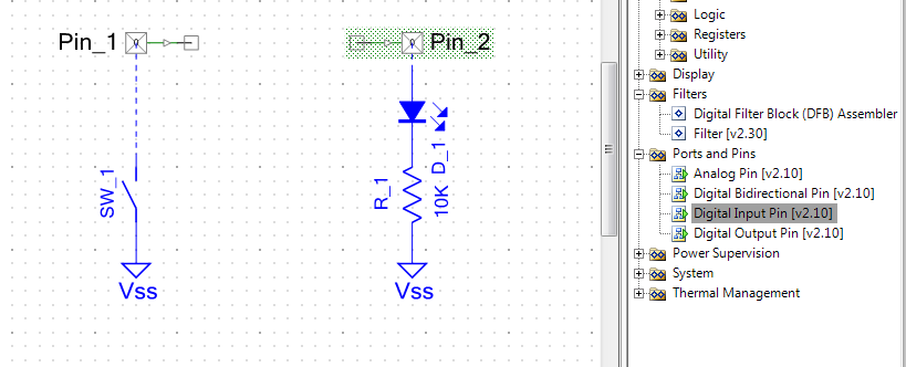
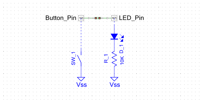
I've pulled a couple of components over from the component catalog, here: from "Ports and Pins", a "Digital Input Pin" and a "Digital Output Pin", and from the off-chip portion, a switch, resistor, and LED. Again, those off-chip parts are purely aesthetic and have no more effect on the generated output than if you were to draw a picture of a butterfly on the schematic.
To wire them up, either select the "Wire" tool on the left edge of the schematic window, or press the 'w' key.
Double click Pin_1, the input pin. You'll get the component configuration window, where you can set all the various parameters that define the part at build time.
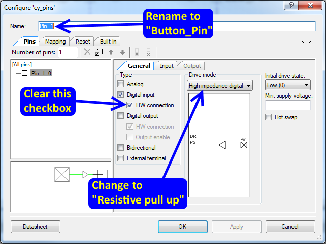
From here, you can do an awful lot. For now, we're going to do three things: rename the pin, change the drive mode to "Resistive pull up" and clear the "HW connection" checkbox. "HW connection" provides a place to attach a component internally; for example, a PWM output or an input to a counter. If you don't want to attach something to it, you have to disable this checkbox or the IDE will complain.
Rename the pin, too; the pin's name is important, as it will dictate the name of functions that the IDE will generate to provide a code interface to this object.
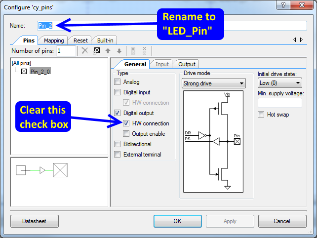
We'll do the same thing for the output pin, except here we can leave the drive mode as-is.
One other thing to notice here is the button in the lower left: "Datasheet". Each of these components has a very well written datasheet describing what it does, what every setting in the configuration window if for, how to use the API, and how much of your available digital or analog resources you can expect it to consume.
The last thing to do before we can write some code is to assign these logical pins to a physical pin on the package. To do this, open the .cydwr file from the workspace explorer on the left side of the window. You'll get something that looks like this:
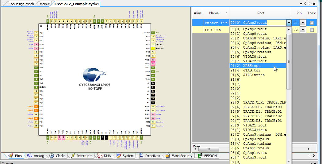
Ignore the tabs along the bottom edge for now.
On the right side, there's a list of pin objects, port pins, and physical pin numbers. If you don't assign a pin to a physical port, the IDE will do it for you. On the FreeSoC2, the user button is attached to port 1, pin 2, and the user LED to port 6, pin 7, so let's make those assignments now. Note how the "lock" box becomes checked when you change the setting; that prevents the IDE from reassigning that pin.
You'll also notice that many pins have some extra text associate with their port/pin information; for example, P1.2 is also labeled as "XRES:opt". These are special functions that can be associated with the pin for improved performance, rather than mandates that a given pin be used for a specific function.
Software
Let's write some code!
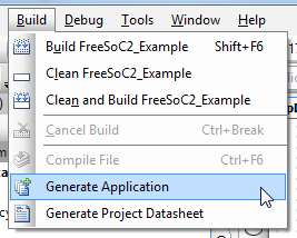
The first thing to do is to create the necessary API files to support the hardware you placed in the schematic earlier. To do that, choose the "Generate Application" item in the "Build" menu.
You'll note that a bunch of new files pop up in the workspace explorer. These are the support files for the components. Don't edit them. They are, in fact, just standard C files, and you could rework them to fit your needs, but the IDE can, and does, frequently regenerate those files, which would wipe out any changes you've made.
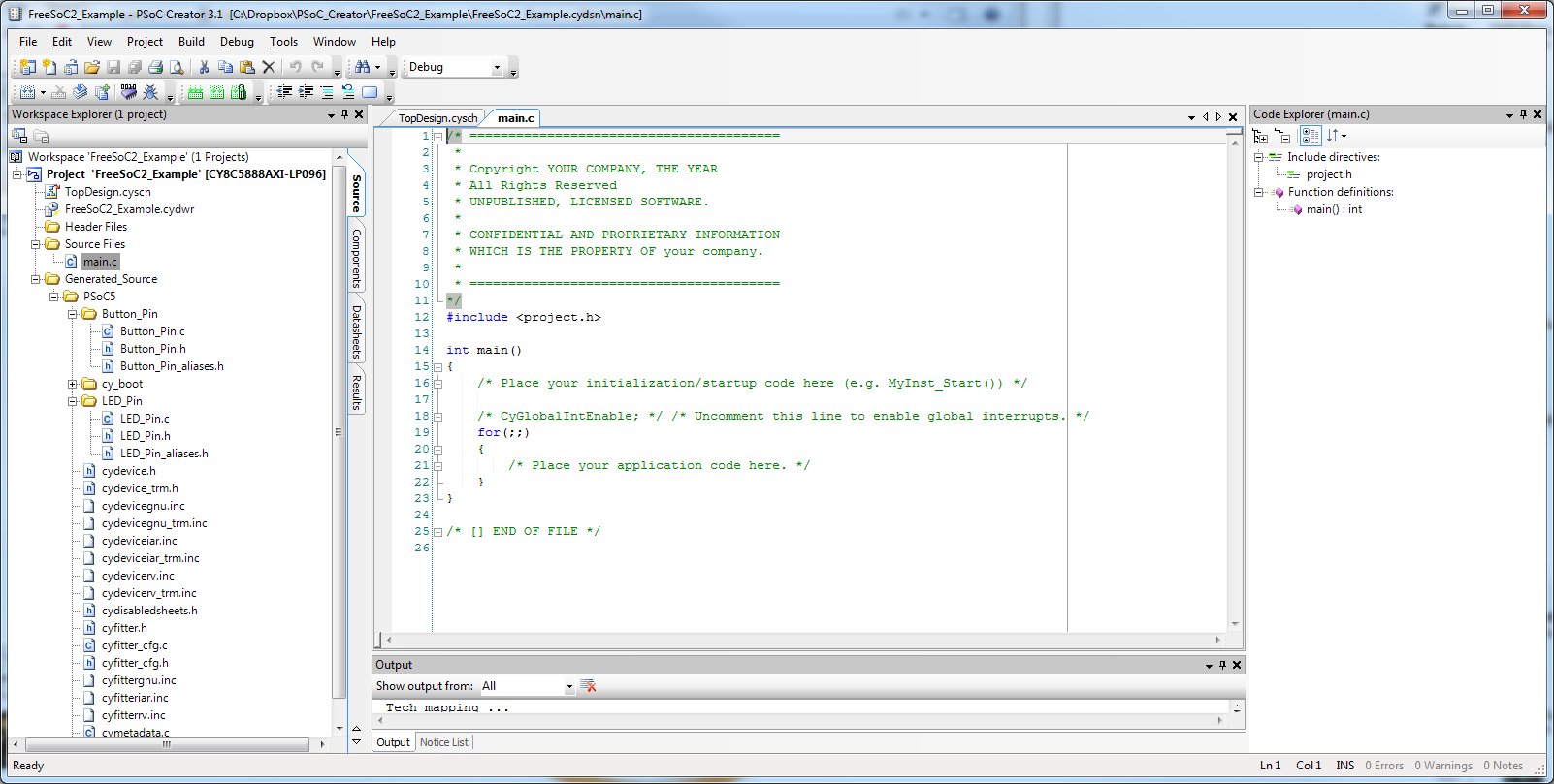
Here's our main.c file. This is automatically generated, and you can safely alter it without worrying about the IDE breaking it.
Put this code into the for(;;) loop section:
language:c
if (Button_Pin_Read() == 0)
{
  LED_Pin_Write(1);
}
else
{
  LED_Pin_Write(0);
}
It's pretty simple: turn the LED on when the button is pressed and off when it's released.
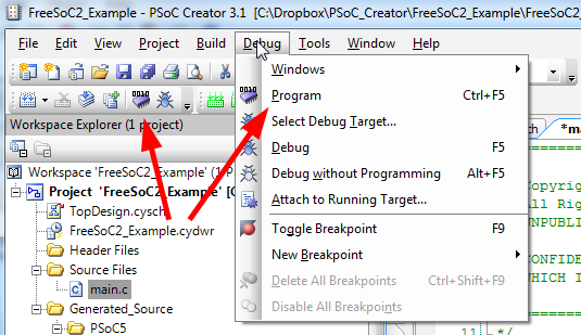
Now, you can upload the code to the processor. The big red arrows in the picture below show three ways of doing so: a menu item in the "Build" menu, a button on the menu bar, and CTRL-F5 as a hotkey. Make sure that you're connected to the "Debug" USB port! The "Target" port can only be used for uploading code via a bootloader.
The IDE will automatically save all open, changed files, and initiate a rebuild if necessary. Then, it will find any attached programmers and automatically connect and program.
Hardware
This is the PSoC, though, right? So, we can skip the code part, entirely!
Delete the code you just added to the main.c file, and let's do it in the schematic instead.
Open up those pin configuration windows again, and this time check the "HW connection" checkboxes. If you don't do this, you won't be able to connect the pins to one another.
Then, add a piece of wire (the wire tool can be activated by typing "w" or with the toolbar on the left edge of the schematic) between the little boxes that appeared on those pin symbols, like this:
Now, click that "Program" button again, and let's see what happens...
Whoops! The light is off when the button is pressed and on when it's release! The polarity's reversed. We need an inverter. Find the "Not" component in the Component Catalog, under Digital/Logic. Don't forget to delete the wire between the two pins before connecting the inverter!
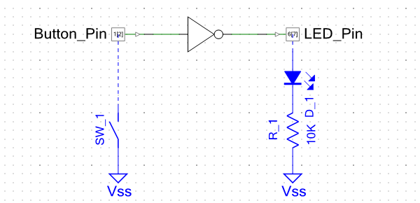
Ah! There we go. Now it works right, and it required no code at all, nor any changes to the physical hardware outside the device.
Keep going!
There are a lot of examples provided with Creator; they can be added to an existing workspace from the "Examples..." menu item in the "File" menu.
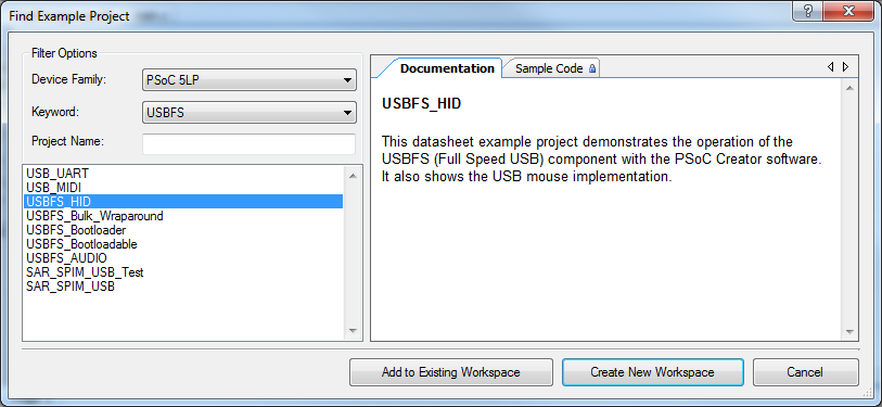
Examples are sorted by keyword; there's an example for almost every problem.
Resources and Going Further
The PSoC community is robust and thriving, and Cypress has provided a lot of really good resources for hobbyists and professional engineers alike:
- 100 projects in 100 days - Cypress, in conjunction with Element-14, created 100 projects and released them to the community. These are based on the PSoC4, but adapt well to the PSoC5LP.
- Forums - Cypress also has a thriving forum community.
- Reddit - There's a fairly active subreddit for the PSoC, as well.
- Video tutorials - Official PSoC Creator training videos. These are information dense and super helpful.
For more FreeSoC2 fun, check out these other SparkFun tutorials...