Flashlight Kit
 M-Short
 Introduction
The Flashlight Soldering Kit is a basic soldering kit designed to help teach the basics of through hole soldering and circuit design. This tutorial will go over the basics of a circuit, how to solder, and show you how to build your own flashlight.
Required Tools
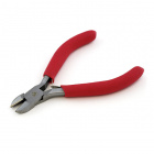
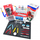
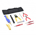
To build this you will need a few basic tools such as a soldering iron, solder, and snippers. If you have never soldered before and are looking for a basic setup, the Beginners Tool Kit is a great place to start.


Suggested Reading
Here are a few basic tutorials on some of the concepts that we will cover. There are also links throughout the tutorial to give you more information on a topic if you are confused or just interested in learning more.
How to Solder: Through-Hole Soldering
Resistors
Light-Emitting Diodes (LEDs)
Polarity
Hardware Overview
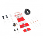
Contents
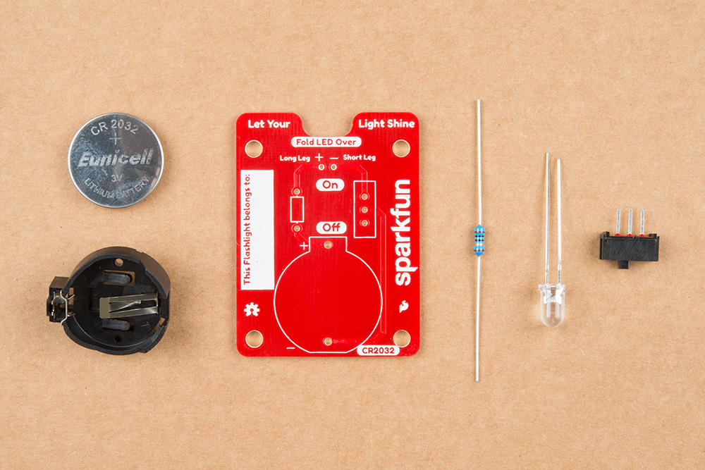
Inside your kit you'll find a few parts. There should be a PCB, a small coin cell battery, a battery holder, an LED, a resistor, and a switch. We'll get into what each of these components looks like and what they do in the next section. Missing any parts? Sometimes one of those tiny little components can get misplaced. If you're missing any parts contact our customer service team, and we'll get you those missing parts in a jiffy.
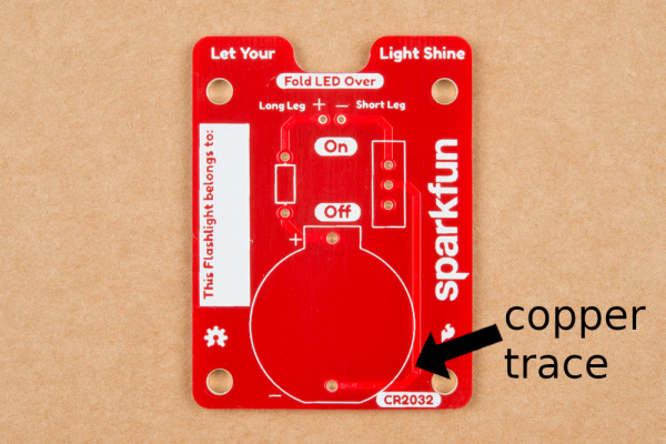
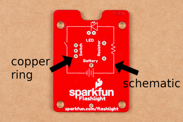
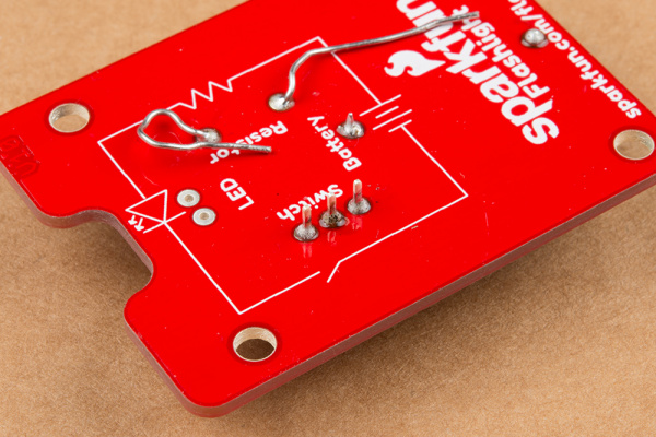
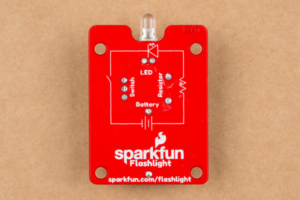
Before we get started lets take a basic look at the PCB. On the front you can see markings and outlines for the 4 different components as well as some labels. You can also see the traces on the board and how they go from one component to another making a complete circle. On the back you see that the holes have a copper ring around them so you can solder them. You'll also see a schematic of the circuit showing all 4 components (with each labeled). We'll get into what each component does in a minute.
|
|
| Front of the Board | Back of the Board |
Flashlight Circuit
The Circuit
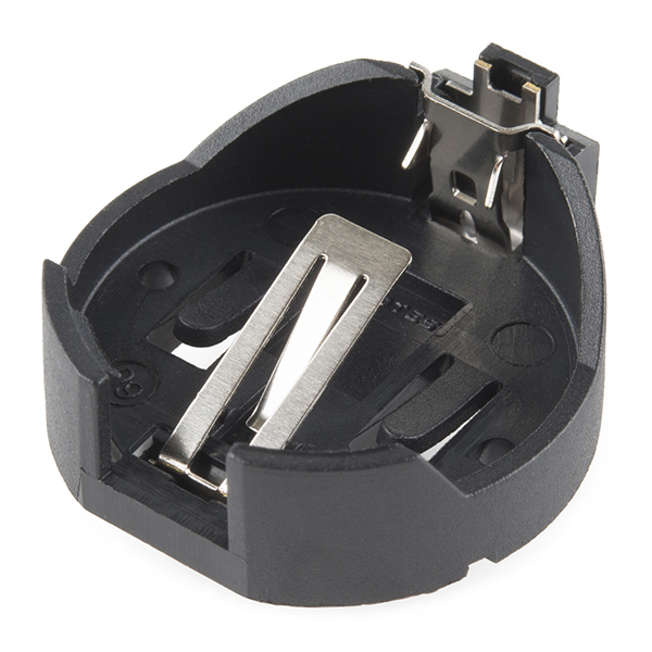
So, what does our circuit do? A completed circuit is a path where electrons can flow. Consider the battery our source of electrons. Current is how we measure the flow of those electrons. Starting with the positive end of the battery, you can see the path it takes along the left side of our PCB up to the resistor. Batteries are basically our power house that stores power and outputs that power in terms of current (how fast the electrons are moving) and the voltage (the amount of pressure pushing those electrons through the circuit).
 |
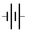 |
| Battery Holder | Schematic Notation for Battery |
The Resistor
The resistor is like a tube that restricts the amount of current that can get through. This resistor minimizes the current that gets to your LED so we don't give the LED too much current and destroy it. If you are curious how this works you can check out our LED tutorial to see how to properly size a resistor. If you look closely at your resistor you'll notice some color bands. In this kit we use a 5 band resistor (brown, black, black, gold, brown); this is a 10 Ohm resistor with a 1% tolerance. Resistors are not directional, meaning they can be used in the circuit in either a forwards configuration (brown, black, black, gold, brown) or a backwards configuration (brown, gold, black, black, brown) and still function correctly.
 |
 |
| Resistor | Schematic Notation for Resistor |
The LED
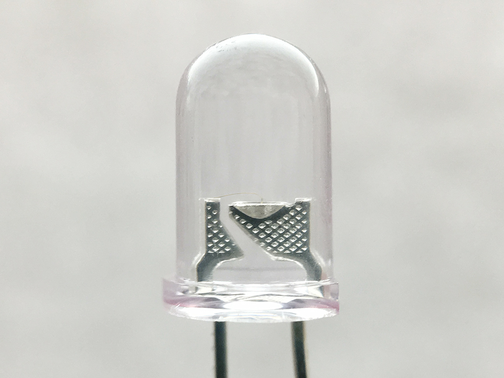
Next we have the LED. LED stands for light emitting diode. A diode is 2 pieces of semiconductor placed together to allow current to only flow in one direction. This is one of the reasons your LED is polarized (meaning it matters which way you hook it up). The current can only flow from the positive side (anode) to the negative side (cathode). In this case we are using a light emitting diode, which does exactly what it sounds like. It is a diode that emits light which is very convenient for a flashlight. Using different substances in the diode allow for different colors; for our flashlight we chose a white LED.
 |
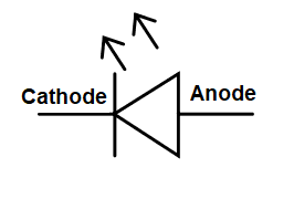 |
| LED | Schematic Notation for LED |
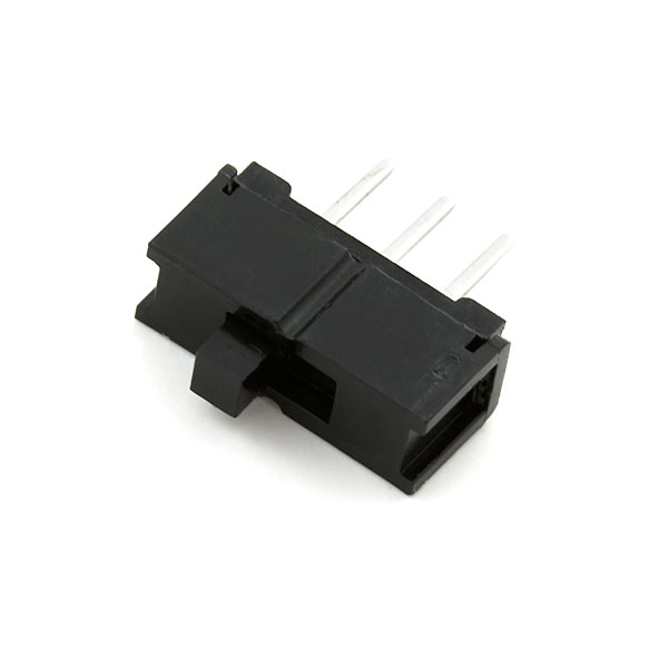
The Switch
Last we have our switch. A switch is actually a mechanical part, meaning you have to physically move the switch Physically moving the switch will connect the negative pin from your LED to the negative pin of your battery, thus completing the circuit. Flip the switch the other way and the switch physically disconnects those 2 components.
 |
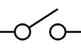 |
| Switch | Schematic Notation for Switch |
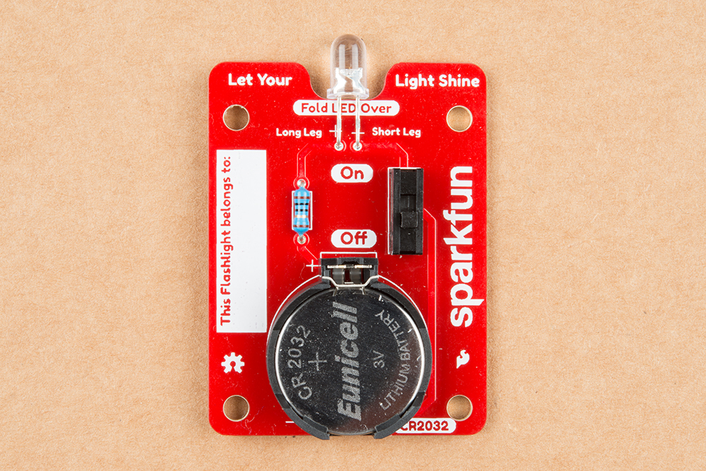
The Schematic
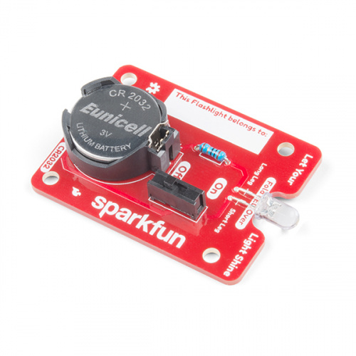
Once you put everything together, our electrons will flow (when the switch is in the On position) and our flashlight will turn on. Here is a picture of the completed board and the full schematic (also found on the back of the PCB).
 |
 |
| Completed Flashlight | Schematic Notation for Completed Circuit |
How to Solder
Soldering is basically melting metal. Solder is a specially formulated metal with a relatively low melting point. For example the melting point of solder is typically about 370F(188C) to 428F(220C) where as the melting point of copper is 1984 F (1085C). With a soldering iron we can melt the solder in order to connect two pieces of metal. This connection is both mechanical (physically holds the parts together) and electrical (allows electricity to flow between them). If you look at the front of your PCB, you'll can see the copper traces that are run just under the surface and are exposed in the holes we are going to solder to.
A Tip About Tips
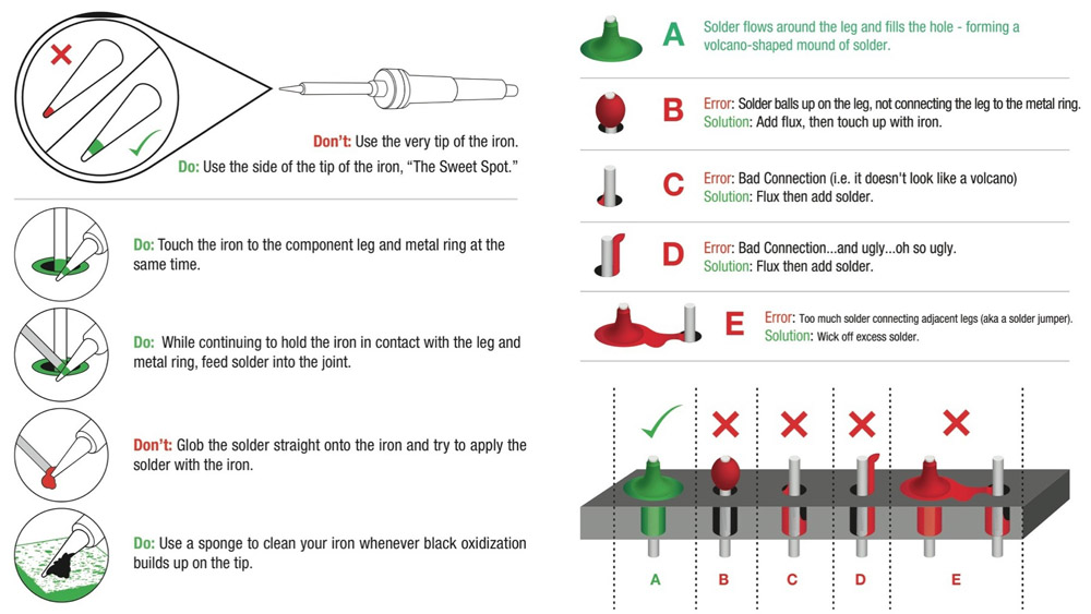
So, how do you solder? The goal is to heat the metal pads and the components and then let them melt the solder. Do not try to melt the solder and then wipe it where you want it as that will both cause bad joints and get pretty messy. Soldering irons come with many different tips. While finer points may work better for finer work, fatter tips hold heat better and therefore can be used more quickly and efficiently than finer points. Ultimately it is a personal choice, but the tip your iron comes with is a good place to start.
Position is Everything
When soldering you'll want to avoid trying to heat things with the point of the iron. Use the side near the tip for the most effective heat transfer. Place the iron next to the joint between the board and the component, wait about 1 second and then feed about 1/2in (about 1cm) of solder into the joint. It should melt immediately and make a nice shiny mountain of solder. Once you have enough solder remove the solder and then the iron. If you remove the iron first your roll of solder will be stuck to your joint. If this happens don't worry, just heat up the joint, remove the solder (and then the iron) and you are good to go. If it doesn't melt right away you may need to wait a bit longer, check your iron placement, clean your tip, or increase the temperature of your iron.
Check out the Vimeo version here.
Keep it Clean
Don't forget to clean your tip periodically! I usually try to do this every time I put the iron back in the stand. No matter what you do you, you are likely to end up with burnt on gunk on the end of your iron. A lot of that will be flux (a substance used to make the solder flow better that is actually part of a lot of solders you buy), or old burnt solder. Most soldering iron stands will have a spot for a sponge to wipe your tip on. You will need to use either a brass sponge or a regular sponge that is wet to wipe off your tip. For more soldering tips and info check out our soldering tutorial.
Click for a larger image.
Assembly Guide
We are going to start with the smallest components first and add parts in as they get larger. This makes it easier to get your components to stay put when you are soldering them in.
Attaching the Resistor
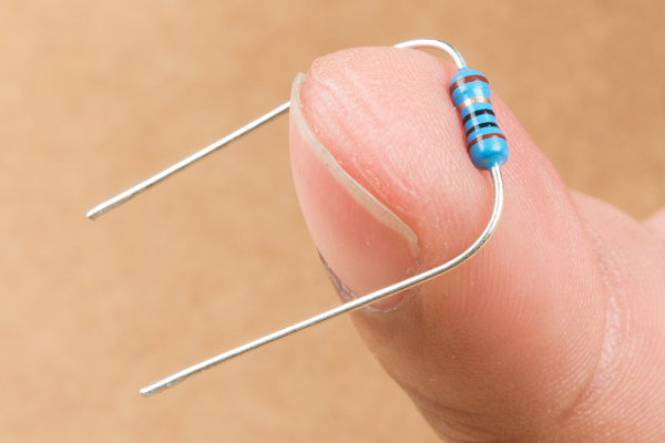
First we'll add the resistor. Bend the ends down at a right angle so that it looks like a 'U'. Personally I like to just bend them over my finger, but depending on your finger size this may or may not work well. We are then going to insert each end into the board in the spot labeled "Resistor". Turn the board over and pull the leads through. Your resistor should be sitting pretty flush to the PCB. It doesn't have to be perfect, but the closer it is, the neater it will look. Now you can go ahead and bend the legs over a bit to help hold everything in place. Then solder the 2 joints (see above for correct solder methods).
 |
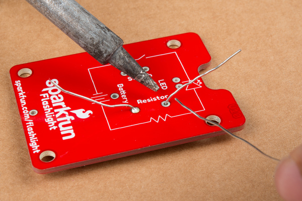 |
| Shaping the Resistor | Solder Points for Resistor Legs |
Attaching the Battery Holder
Next we are going to solder on the battery holder. Make sure you put it in the right way! The board will have an outline on it showing which way it goes. Solder the 2 pins on the bottom side of the board. The battery holder should be fairly flush to the board. While it doesn't need to be perfectly flush, it needs to be flush enough that both feet go through the board and can be soldered. If you solder in the first pin and find that it isn't sitting flush don't worry. Put pressure on the board with one hand and heat up the joint with the other hand. Once the solder melts the part should snap into place.
Attaching the Switch
Next is the switch. Insert the switch (either direction is fine) and flip the board over Solder the 3 switch pins into place. Again the switch should be fairly flush to the board. Look at that, you are becoming a pro at this!
 |
 |
| Switch Placement on the Front of the Board | Solder Points for the Switch on the Back of the Board |
Attaching the LED
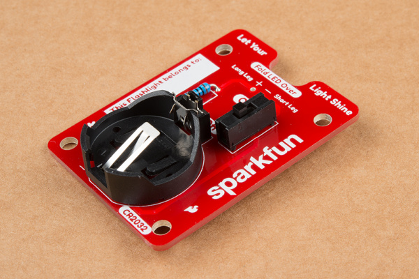
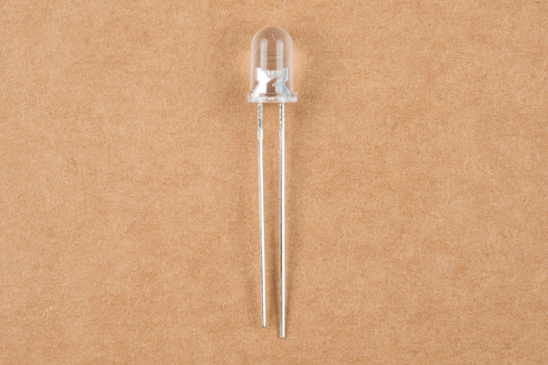
The final solder step is the LED. LEDs are polarized, meaning the direction you insert the LED matters. If you take a look at your LED you'll notice one leg is longer than the other. Insert the LED with the long leg on the side labeled "Long Leg". Insert the LED almost to the board and bend it over so it lays in the slot on the top of the PCB. It doesn't have to be exact, but this will allow your flashlight to shine forward instead of straight up and in your eyes. Then you can bend the legs back on the back of the PCB to help hold it in place and solder the legs.
 |
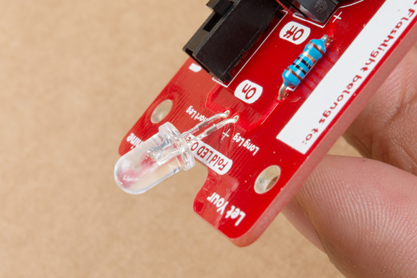 |
| LED - Note One Leg is Longer! | Placement and Shaping of LED |
Clean Up
Next is a bit of clean up. Clip off all your extra leads on the back side of the board; you don't want things making connections they shouldn't and the switch pins can poke you if you are not careful. Get a good pair of cutters and snip those leads off! The last step is to put your battery in, make sure the switch is in the "On" position, and let your light shine!
 |
 |
| Front of the Finished Board | Back of the Finished Board |
Troubleshooting
Flashlight Not Turning On
- Make sure you turned the switch to the On position
- Make sure you inserted a new CR2032 battery (and that it is in + side up)
- Double check all solder joints to make sure they have a good connection
- Make sure you soldered your LED in the correct way
- Make sure you clipped your leads so you don't have any shorts
Flashlight Flickering
- Make sure all components are soldered in place well
- Make sure battery is in securely
- Make sure switch is pushed all the way up
- Make sure there are no "extra" connections - the leads on the back side of the board should be cleanly clipped.
Flashlight Is Dim
- Make sure resistor value is 10Ω (brown-black-black-gold-brown)
- Replace battery as needed
Resources and Going Further
Now that your flashlight is lighting everything up, where do you go from here? Check out some of our different tools as well as some additional kits you can solder together. Also, check out some of our other soldering tutorials, or just start building your own projects.
Resources for This Kit:
For more information, check out the resources below:
Soldering Kits
Soldering Tools and Kits

More Soldering Tutorials
Looking for more of a challenge? Try soldering the same circuit together without using a PCB like the 3D Printed Illuminated Wand Prop!
3D Printed Illuminated Wand Prop
Looking for more soldering tutorials? Check out some of these related tutorials: