First FPGA Project - Getting Fancy with PWM
Introduction
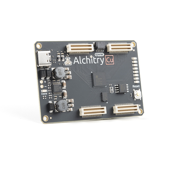
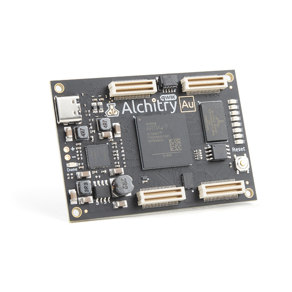
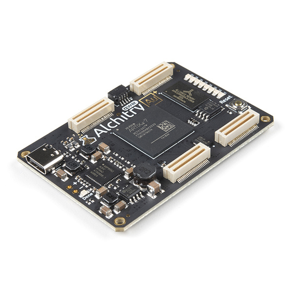
When you first buy an Alchitry Au+, Alchitry Au, or Alchitry Cu board, the default FPGA configuration creates a fancy wave effect on the LEDs. In this tutorial we are going to walk through different steps for how to make something like this. It will be a great overview for how to approach a design and various things to consider given that we are working with hardware.
Let's dig in and see how all this works!
I’m going to assume you already have the tools setup and are working in Alchitry Labs using Lucid with an Alchitry Au or Cu. You should also have read the previous tutorial, Programming an FPGA, to get down some of the fundamentals.
Programming an FPGA
Required Materials
To follow along with this tutorial, you will need the following materials. You may not need everything though depending on what you have. Add it to your cart, read through the guide, and adjust the cart as necessary.
Suggested Reading
If you aren’t familiar with the following concepts, we recommend checking out these tutorials before continuing.
Programming an FPGA
How Does an FPGA Work?
Pulse Width Modulation
Before we jump into anything FPGA specific, we need to quickly cover what pulse width modulation (aka PWM) is.
PWM is a technique used by digital systems to approximate analog values. This is done by creating a series of pulses with a specific duty cycle. A duty cycle is simply the percentage of time a signal is high. A 100% duty cycle would simply be a fully on signal. A 50% duty cycle would have equal parts high and low.
The following is an example of a PWM signal with a 33% duty cycle.

If the frequency of these pulses is high enough, in some applications, it can seem as if we are producing a value between high and low. This is useful for varying the brightness of LEDs.
LEDs are actually incredibly fast to turn on and off so when applying PWM signals to them they actually flicker. Luckily our eyes will average out this flickering if it is done fast enough making them look solid but dimmer. This effect is called persistence of vision.
Creating Pulses
We need to create a module that accepts an input value and produces a PWM signal with a duty cycle proportional to it.
This can be pretty easily done using a counter.
If we have a free-running counter, meaning it continuously is incremented, we can use this to set an output depending on the counter’s state.
If the threshold we are comparing to the counter is above the counter’s current value, we can output 1 and 0 otherwise. This would look like the following:

Here, the compare value is 1/3 the max value of the counter so the duty cycle is 33%.
If we change the compare value, we change the duty cycle.

Now the duty cycle is 66% as the compare value was increased.
We can make a simple module that will do this:
module pwm #(
    COMP_LENGTH = 8 : COMP_LENGTH > 0
  )(
    input clk,  // clock
    input rst,  // reset
    input compare[COMP_LENGTH],
    output pwm
  ) {

  .clk(clk) {
    .rst(rst) {
      dff counter[COMP_LENGTH];
    }
  }

  always {
    counter.d = counter.q + 1; // free running counter
    pwm = counter.q < compare;
  }
}
You could use this module to control an LED’s brightness and it would work pretty well. However, there are a few issues with it.
Glitches
First, this module isn’t glitch free. In the case of an LED, this doesn’t matter. However, for something that the width of each pulse actually matters (like a servo), this is important.
What do I mean by glitch free? Well imagine the current counter value is 25 and the current compare value is 10. The output is currently low since the counter is higher than the compare value. But what if we now change the compare value to 30? We will get a pulse 5 cycles long.
We never requested a pulse 5 cycles long. We were requesting pulses of 10 cycles then pulses of 30 cycles.
To fix this we need to only update the compare value when the counter is at its maximum value. We will need to save the current compare value until then using a DFF.
 module pwm #(
    COMP_LENGTH = 8 : COMP_LENGTH > 0
  )(
    input clk,  // clock
    input rst,  // reset
    input compare[COMP_LENGTH],
    output pwm
  ) {

  .clk(clk) {
    .rst(rst) {
      dff counter[COMP_LENGTH];
      dff last_comp[COMP_LENGTH];
    }
  }

  always {
    counter.d = counter.q + 1; // free running counter
    pwm = counter.q < last_comp.q;
    if (&counter.q)
      last_comp.d = compare;
  }
}
You can see I’m now comparing the counter with last_comp.q instead of the raw input compare value. I’m updating the value of last_comp with the input compare only when counter.q is all 1’s, aka its max value.
To check if counter.q is its max value, I’m using what is known as a reduction operator. In this case, I’m using the AND reduction operator. By putting the & in front of a value, every bit of that value will be AND’d with all the other bits. This will return 1 only if every bit is 1.
You can also use this with OR by using the pipe, |, symbol. This will return 1 if any of the bits are 1.
The XOR version uses a carrot, ^, and will return 1 if there are an odd number of 1s.
Using the reduction operator instead of an == comparison is convenient in a case like this because the width of counter.q is specified as a parameter. Its max value changes depending on the width but the max value will always be when the individual bits are all 1.
Now, no matter when or what we change compare to, the module will only ever output pulses of the width we have requested.
Prescaler
The next issue has to do with the fact that we can’t adjust the frequency of the pulses. They are simply a factor of how fast the clock is and how wide our counter is.
This is actually an issue with the LED because each time you turn it on and off you waste a little power charging and discharging capacitance on the line. If your frequency is too high, this parasitic loss becomes dominant and the LED will lose brightness. We want the pulse frequency to be fast enough we can’t see it but not obscenely faster. Something like 200Hz works great.
With an 8 bit counter, it is currently running at 100MHz/256 = 390.6KHz or roughly 2000 times faster than we want.
To adjust this, we can add a pre-scaler. This is a second counter that is used to increment our main counter after a certain number of cycles.
The simplest and most efficient way to do this is to add some extra bits to your main counter and only look at the most significant bits of it. By adding just one bit to the end we effectively divide the rate by 2. Two bits will divide it by 4 and so on in powers of 2.
module pwm #(
    PRESCALER = 11 : PRESCALER >= 0,
    COMP_LENGTH = 8 : COMP_LENGTH > 0
  )(
    input clk,  // clock
    input rst,  // reset
    input compare[COMP_LENGTH],
    output pwm
  ) {

  .clk(clk) {
    .rst(rst) {
      dff counter[COMP_LENGTH+PRESCALER];
      dff last_comp[COMP_LENGTH];
    }
  }

  always {
    counter.d = counter.q + 1; // free running counter
    pwm = counter.q[PRESCALER+:COMP_LENGTH] < last_comp.q;
    if (&counter.q)
      last_comp.d = compare;
  }
}
I added a parameter named PRESCALER which is the number of bits to use as a prescaler. This is added to COMP_LENGTH to create the width of the counter.
In the comparison, I used the start-width bit indexing syntax to select COMP_LENGTH bits starting at PRESCALER and going up. If PRESCALER is 0 and COMP_LENGTH is 8, this would read [0+:8] which would select bits 0-7. If PRESCALER was 11, this would read [11+:8] and select bits 11-18.
Top Value
Adding the prescaler gives you a crude way to adjust the frequency and is plenty for controlling LEDs. However, some applications require a more specific frequency. For these, you need to be able to set a custom top value.
The top value is simply the value that the counter will reset. In all our previous examples, this value has been the maximum value the counter could hold as it will reset automatically.
We can add an if statement to check the counter value and reset it manually to increase the frequency.
module pwm #(
    PRESCALER = 11 : PRESCALER >= 0,
    COMP_LENGTH = 8 : COMP_LENGTH > 0,
    TOP = $pow(2,COMP_LENGTH)-1 : TOP >= 0 && TOP < $pow(2,COMP_LENGTH)
  )(
    input clk,  // clock
    input rst,  // reset
    input compare[COMP_LENGTH],
    output pwm
  ) {

  .clk(clk) {
    .rst(rst) {
      dff counter[COMP_LENGTH+PRESCALER];
      dff last_comp[COMP_LENGTH];
    }
  }

  always {
    counter.d = counter.q + 1; // free running counter
    if (counter.q == TOP) {    // if we reach the TOP
      counter.d = 0;           // reset the counter
      last_comp.d = compare;   // and save the compare value
    }

    pwm = counter.q[PRESCALER+:COMP_LENGTH] < last_comp.q;
  }
}
In this version, I added the parameter TOP and set its default value to be its maximum value.
I used the $pow() function to compute the value of 2^COMP_LENGTH. This function like $clog2() used in the previous tutorial are computed during synthesis and aren’t in your design. Because of this, they can only be used with constant known values.
I also moved the updating of last_comp to be when the counter reaches TOP instead of it being all 1’s.
This is now a full fledged PWM module, but we really didn’t need to write it.
Components Library
Alchitry Labs has a bunch of built-in components that can be added to your project to do common tasks, such as PWM.

Go to Project->Add Components to open the Component Library.
Here you can go to LED Effects and select PWM.
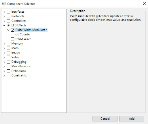
Click Add to add the component to your project.
You will find it under the Components branch in your project tree.
module pwm #(
    WIDTH = 8 : WIDTH > 0, // resolution of PWM counter
    TOP = 0   : TOP >= 0,  // max value of counter
    DIV = 0   : DIV >= 0   // clock pre-scaler
  )(
    input clk,          // clock
    input rst,          // reset
    input value[WIDTH], // duty cycle value
    input update,       // new value flag
    output pulse        // PWM output
  ){

  .clk(clk) {
    .rst(rst) {
      counter ctr(#SIZE(WIDTH), #DIV(DIV), #TOP(TOP));
      dff curValue[WIDTH];
      dff needUpdate;
    }
    // nextValue doesn't need reset
    dff nextValue[WIDTH];
  }

  always {
    // if ctr.value is 0 and we need to update
    if (!|ctr.value && needUpdate.q) {
      curValue.d = nextValue.q; // set our new value
      needUpdate.d = 0;         // don't need update now
    }

    // if value is valid
    if (update) {
      nextValue.d = value; // save it
      needUpdate.d = 1;    // flag for update
    }

    // if the counter is less than the set
    // value output 1, otherwise output 0
    pulse = ctr.value < curValue.q;
  }
}
This version is very similar to ours with one exception. It assumes that the input value, which is used as the compare value, is only valid when update is 1.
It allows you to specify a new value at any time and it will save it until the new value can be used as the compare value.
There are some other differences as this component is actually using another component, a counter. The counter component is used to take care of the pre-scaling and top resetting for us.
Pulsing an LED
Armed with the PWM module from the component library, we can create a new module that will pulse an LED.
To pulse an LED we need to create values to feed to the PWM module that oscillate slowly between the minimum and maximum values. For simplicity, we are going to use a triangular waveform. You could get fancy and use something line a sine wave but this would be significantly more complicated.
By triangular waveform, I mean generating a counter value that linearly increases to the max value then linearly decreases to the minimum value before repeating.
So how can we efficiently create a triangular waveform? A free running counter will generate a saw-tooth waveform, meaning it linearly increases to the maximum then jumps to the minimum.
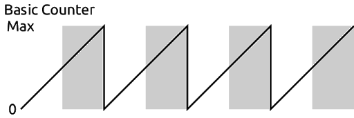
We can exploit this counter with a slight modification to create our waveform. First notice the gray shaded regions in the image above. These are where the MSB in the counter is 1.
If we remove the MSB from the counter we would see a waveform like this:

Notice the frequency has doubled and the max value is halved.
However, if we can flip the shaded regions we will have our triangular waveform.

This is great but how do we flip the value from the counter? One way is to simply subtract the value of the counter from max/2. However, there is a super efficient binary shortcut for this.
If instead of subtracting the value, we just invert the bits of the counter we get the same result. For example if we are counting from 0-7 the first three numbers are 000, 001, and 010. If we invert the bits that become 111, 110, 101, or 7, 6, 5. Simply by inverting each bit we can change the counter from counting up to counting down.
Putting this together into a module looks like this.
module pulse (
    input clk,  // clock
    input rst,  // reset
    output led  // output to led
  ) {

  .clk(clk) {
    .rst(rst) {
      pwm pwm(#WIDTH(8), #DIV(11));  // PWM component
      dff ctr[27];                   // counter
    }
  }

  always {
    led = pwm.pulse;    // connect the PWM output to the led

    ctr.d = ctr.q + 1;  // increment the counter

    pwm.update = 1;     // always update

    // connect the triangular waveform to the PWM module
    pwm.value = ctr.q[ctr.WIDTH-2-:pwm.value.WIDTH] ^ pwm.value.WIDTHx{ctr.q[ctr.WIDTH-1]};
  }
}
The line that does the inversion has some new syntax so let’s break that down.
First we need to select the bits of the counter that will be used for the PWM values. These are the eight MSBs of the counter excluding the first once since we are using that to know when to invert the value.
Every signal in Lucid has a constant WIDTH associated with it. This can be used to get how many bits make up the signal. So ctr.WIDTH is 27 in this case. We can use ctr.WIDTH-2 to get the second MSB.
We can then use pwm.value.WIDTH to get the width of the value input of pwm. Using the down-to syntax we can select pwm.value.WIDTH bits of ctr.q starting at ctr.WIDTH-2 and going down.
We are then doing a bitwise XOR using the ^ operator. This operator takes two signals of equal dimensions and XORs each of the corresponding bits together. We are using this since if you XOR a value with 0 it returns the value but if you XOR a value with 1 it inverts it.
We need to duplicate the MSB of our counter so that it is as many bits as pwm.value. To do this we use the duplication operator. This takes the format of num x{ value } where num is the number of times to duplicate value.
The space between num and x is optional but is typically written without it.
This line could’ve been written with numbers instead of using the WIDTH constants like this.
pwm.value = ctr.q[25-:8] ^ 8x{ctr.q[26]};
However, by using the WIDTH constants we can change the length of the counter or the pwm component without having to change anything else in our code.
We can use this module to drive an LED by adding it to our top-level module.
module au_top (
    input clk,              // 100MHz clock
    input rst_n,            // reset button (active low)
    output led [8],         // 8 user controllable LEDs
    input usb_rx,           // USB->Serial input
    output usb_tx           // USB->Serial output
  ) {

  sig rst;                  // reset signal

  .clk(clk) {
    // The reset conditioner is used to synchronize the reset signal to the FPGA
    // clock. This ensures the entire FPGA comes out of reset at the same time.
    reset_conditioner reset_cond;

    .rst(rst) {
      pulse pulse;
    }
  }

  always {
    reset_cond.in = ~rst_n; // input raw inverted reset signal
    rst = reset_cond.out;   // conditioned reset

    led = pulse.led;        // connect the LED to the pulser

    usb_tx = usb_rx;        // echo the serial data
  }
}
If you build and load this onto your board the first LED should now be slowly pulsing.
Creating a Wave
We now need to get all eight LEDs pulsing out of sync with each other to make the wave effect. We can do this by setting the initial value of the counter to something different for each one.
DFFs have a parameter named INIT. This parameter allows us to set a value that will be assigned to the DFF upon configuration of the FPGA or reset if the DFF has a reset signal. By default, INIT is set to 0.
We can create a parameter in our pulse module called INITIAL_VALUE and pass this along to the DFF.
module pulse #(
    INITIAL_VALUE = 0 : INITIAL_VALUE >= 0 && INITIAL_VALUE < $pow(2,9)
  )(
    input clk,  // clock
    input rst,  // reset
    output led  // output to led
  ) {

  .clk(clk) {
    .rst(rst) {
      pwm pwm(#WIDTH(8), #DIV(11));  // PWM component
      dff ctr[27](#INIT(c{INITIAL_VALUE, 18b0}));  // counter
    }
  }

  always {
    led = pwm.pulse;    // connect the PWM output to the led

    ctr.d = ctr.q + 1;  // increment the counter

    pwm.update = 1;     // always update

    // connect the triangular waveform to the PWM module
    pwm.value = ctr.q[ctr.WIDTH-2-:pwm.value.WIDTH] ^ pwm.value.WIDTHx{ctr.q[ctr.WIDTH-1]};
  }
}
Since we are only using 9 bits to determine the value of the PWM duty cycle, I made the INITIAL_VALUE parameter only accept 9 bit values. I then had to pad the value with 18 0s to make it the full 27 bits wide of our counter.
We want the offsets to be evenly spaced across the eight LEDs so each one should be 512/8 = 64 apart.
We can modify the top-level module to instantiate eight of these with different INITIAL_VALUEs.
module au_top (
    input clk,              // 100MHz clock
    input rst_n,            // reset button (active low)
    output led [8],         // 8 user controllable LEDs
    input usb_rx,           // USB->Serial input
    output usb_tx           // USB->Serial output
  ) {

  sig rst;                  // reset signal

  .clk(clk) {
    // The reset conditioner is used to synchronize the reset signal to the FPGA
    // clock. This ensures the entire FPGA comes out of reset at the same time.
    reset_conditioner reset_cond;

    .rst(rst) {
      pulse pulse1(#INITIAL_VALUE(0));
      pulse pulse2(#INITIAL_VALUE(64));
      pulse pulse3(#INITIAL_VALUE(64*2));
      pulse pulse4(#INITIAL_VALUE(64*3));
      pulse pulse5(#INITIAL_VALUE(64*4));
      pulse pulse6(#INITIAL_VALUE(64*5));
      pulse pulse7(#INITIAL_VALUE(64*6));
      pulse pulse8(#INITIAL_VALUE(64*7));
    }
  }

  always {
    reset_cond.in = ~rst_n; // input raw inverted reset signal
    rst = reset_cond.out;   // conditioned reset

    led = c{pulse8.led, pulse7.led, pulse6.led, pulse5.led,
      pulse4.led, pulse3.led, pulse2.led, pulse1.led};

    usb_tx = usb_rx;        // echo the serial data
  }
}
If you build and load this onto your board you will see the LED wave pattern we’ve been working towards!
But wait! We aren’t done yet. There are a lot of optimizations we could make to this.
First, count how many counters we have running. Each PWM component has its own counter and each of our pulse modules has another counter. That means we have 16 counters.
Each of the eight PWM counters are identical. They are all the same size, have the same initial value, and all are free-running. The same is true for our pulse counters except they have different initial values.
However, we can get around that too by taking advantage of the circular nature of binary numbers. If we have a free running counter and add a constant value to it, it will seem as if it was just another counter offset by that value. This means our 8 counters could be replaced by one counter and seven adders. Keep in mind that every counter already has an adder in it so this saves all the extra DFFs.
We can combine all the counters together into a single free-running counter.
Finally, we don’t need the glitch free operation of the PWM component since we can ensure that the compare value will only ever update upon overflow of the PWM’s counter as it’ll be using the same counter, just more-significant bits.
All of this is neatly packed away into the PWM Wave component under LED Effects in the component library.
module wave #(
    CTR_LEN = 25 : CTR_LEN >= 9
  )(
    input clk,     // clock
    input rst,     // reset
    output out[8]  // LED output
  ) {

  // counter
  dff ctr[CTR_LEN](.clk(clk),.rst(rst));

  var i;         // for loop var
  sig acmp[8];   // intermediate value
  sig result[9]; // intermediate value

  always {
    // increment the counter
    ctr.d = ctr.q +1;

    // for each output
    for (i = 0; i < 8; i++) {
      // take the top bits of the counter and
      // offset differently them for each output
      result = ctr.q[CTR_LEN-1-:9] + i * 8d64;

      // if the MSB is 1
      if (result[8])
        // invert the result to count down
        acmp = ~result[7:0];
      else // otherwise
        // leave it alone to count up
        acmp = result[7:0];

      // PWM output
      out[i] = acmp > ctr.q[7:0];
    }
  }
}
This module uses some advanced features to make it so compact, namely sig, var, and for loops.
The type var is used to hold a variable. This is a value that shouldn’t actually show up in your design and is used almost exclusively to hold the index value in for loops.
The type sig is used to hold a signal. Basically, these are just a renaming of some other value. They can’t save data like a dff can, but they can be used as placeholders for values to clean up your code.
For loops take the same form seen in many programming languages: for (initialization; check; operation) {...}. The initialization sets the loop var to an initial value. The check is used to set a continuation condition and the operation is “performed” each iteration. Note that the ++ and -- syntax for incrementing and decrementing is only available on var types in this context.
Remember that for loops are really nothing other than a compact way to write something repetitive. The tools must be able to unroll them so they need to have a constant number of iterations.
The first line in the for loop takes advantage of the circular nature we talked about before by adding i * 64 to the counter’s value and naming it result.
Sig types in an always block can be read and written and their values are whatever they were last assigned. So after assigning result the value of the offset counter, we can now use it.
The sig acmp is used to hold the value we will compare with the counter for the PWM signal.
The module could have used the same XOR trick we used before but instead uses an if else statement to accomplish the same thing. In practice these will be implemented the same by the tools and I’d argue the if else format is easier to read. The XOR trick was used before as it was a good way to demonstrate some new syntax.
Finally, each bit of out is assigned depending on the comparison to the first eight bits of the counter. This module also neglects a prescaler on the PWM signal so it isn’t as power efficient as before, but the difference is probably pretty negligible.
We can put this into the top-level module and get the LEDs to wave.
module au_top (
    input clk,              // 100MHz clock
    input rst_n,            // reset button (active low)
    output led [8],         // 8 user controllable LEDs
    input usb_rx,           // USB->Serial input
    output usb_tx           // USB->Serial output
  ) {

  sig rst;                  // reset signal

  .clk(clk) {
    // The reset conditioner is used to synchronize the reset signal to the FPGA
    // clock. This ensures the entire FPGA comes out of reset at the same time.
    reset_conditioner reset_cond;

    .rst(rst) {
      wave wave;
    }
  }

  always {
    reset_cond.in = ~rst_n; // input raw inverted reset signal
    rst = reset_cond.out;   // conditioned reset

    led = wave.out;         // wave the LEDs

    usb_tx = usb_rx;        // echo the serial data
  }
}
This is the exact pattern used in the demo file shipped on the board.
This tutorial’s conclusion may feel a little underwhelming since all of this could have been accomplished simply by adding the wave component to your project and adding two lines to instantiate and connect it. However, hopefully this journey has taught you a bit more about creating FPGA projects.
There is still a lot to cover but you should now be comfortable with the basics to start tinkering.
Troubleshooting
If your product is not working as you expected or you need technical assistance or information, head on over to the Alchitry Forums. This is a great place to do some initial troubleshooting as well as to find and ask for help.
Resources and Going Further
Alchitry's website has more great resources, including tutorials, projects, and the Alchitry Forum.
- Alchitry
- Alchitry Au+ Schematic (PDF)
- Alchitry Au Schematic (PDF)
- Alchitry Cu Schematic (PDF)
- Xilinx Artix 7 User Guide
If you'd like to delve deeper into the world of FPGAs and Lucid, check out "Learning FPGAs: Digital Design for Beginners with Mojo and Lucid HDL" by Justin Rajewski. It's available on Amazon and is a great resource for understanding and ultimately designing your own FPGAs.
We are continually expanding our offering of tutorials and products related to FPGAs. Check out some of the following tutorials!
Programming an FPGA
How Does an FPGA Work?
External IO and Metastability