FemtoBuck Constant Current LED Driver Hookup Guide v13
 SFUptownMaker
 FemtoBuck Overview
Connecting the FemtoBuck
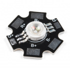
For the version 1.2 of the FemtoBuck, we've increased the voltage ratings on the parts to allow the input voltage to cover the full 36V range of the AL8860. Note that the supply voltage must be at least 6.0V, and should be at least 2-3V higher than the forward voltage of the LED(s) to be driven. You can use the board to drive any high power LED like the ones listed below. Keep in mind that you would need 3x FemtoBucks to control each channel on the triple output high power RGB LED.
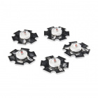
LED - 3W Aluminum PCB (5 Pack, Red)
COM-13106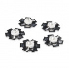
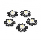
LED - 3W Aluminum PCB (5 Pack, Blue)
COM-13107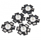
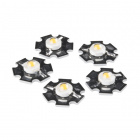
LED - 3W Aluminum PCB (5 Pack, Green)
COM-13185Since the FemtoBuck is a constant current driver, the current drawn from the supply will drop as supply voltage rises. In general, efficiency of the FemtoBuck is around 95%, depending on the input voltage.
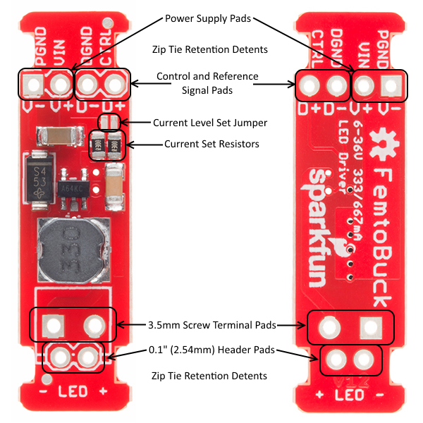
One signal input is provided for dimming control. A ground pin (DGND) is provided to reference against the controlling module for accuracy. Dimming can be done by an analog voltage (20%-100% of max current by varying voltage from .5V-2.5V) or by PWM (so long as PWM minimum voltage is less than .4V and maximum voltage is more than 2.4V) for a full 0-100% range.
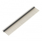
Another ground (PGND) pin is available next to the power supply pin to provide a high-current return path. The spacing on the four holes on the input side is 0.1" for standard headers.

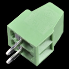
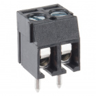
The output side has a 0.1" spaced hole pair as well as a 3.5mm spaced hole pair, to allow the user to attach our 3.5mm screw terminals.
The notches on either end of the board allow you to use a zip tie to secure the wires to the board after soldering them down.
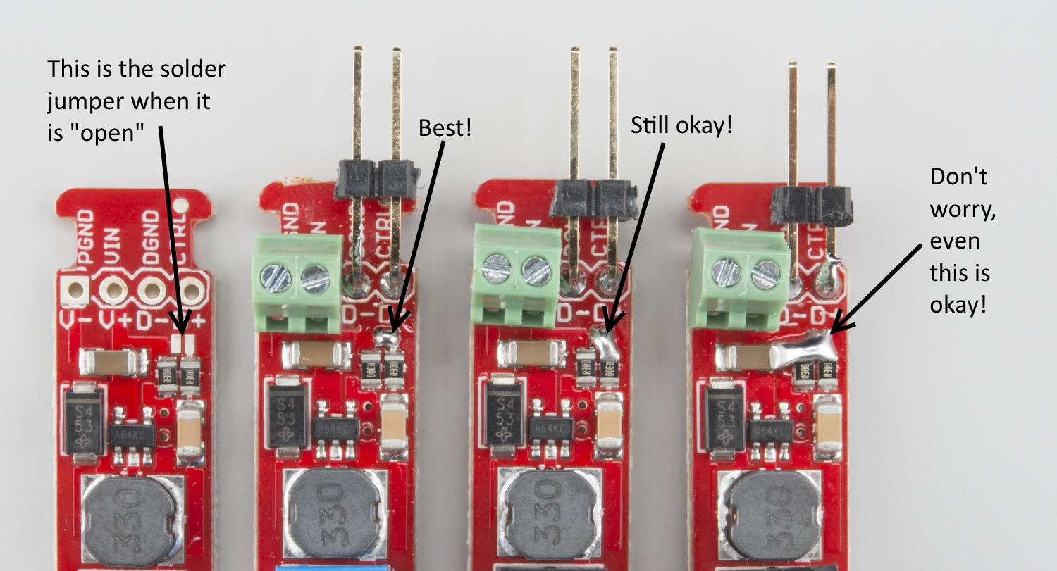
The most recent revision has a small solder jumper, highlighted above, that can be closed with a glob of solder to double the output current from 330mA to 660mA. We suggest closing this jumper before soldering headers, terminals, or wires to the nearby holes. Note that it's very likely that you'll get some solder on the adjacent resistor pads. That's perfectly okay. Those pads will be shorted together when you're done anyway.
Finally, take note of the size of the FemtoBuck. If desired, the entire board can be slid into a piece of 9mm heat shrink tubing to provide insulation and strain relief.
