EL Sequencer/Escudo Dos Hookup Guide
 Toni_K
Hardware Hookup
To get started using the EL Sequencer or EL Escudo Dos, there are a few basic steps that must be completed.
Solder Headers
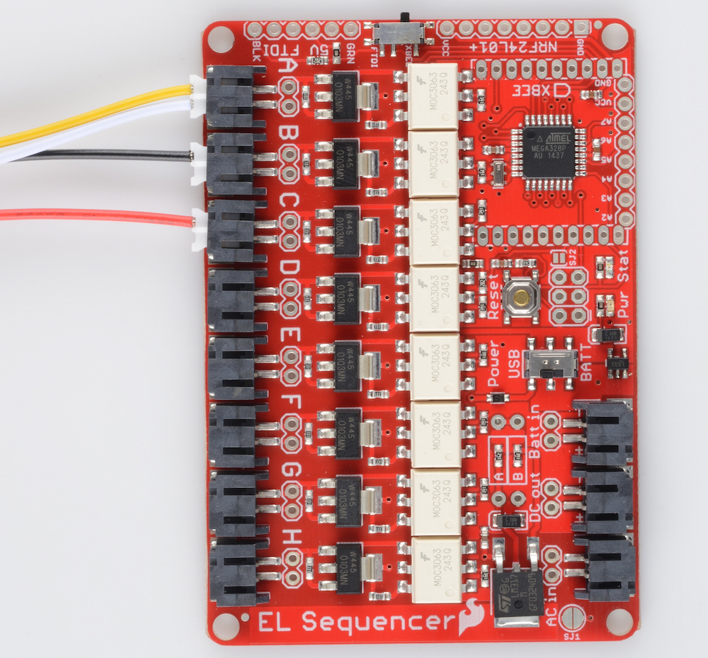
EL Sequencer
At an absolute bare minimum, you must solder 6 pins on the FTDI header. For simplicity's sake, we recommend using male headers (either straight or right angle as these are compatible by default with the FTDI breakout). This will enable you to program the EL Sequencer via an FTDI breakout board.
If you plan on using an XBee unit with your Sequencer, you will also want to solder XBee Sockets to the board. If you plan on using any additional connectors on the board, you will also want to solder those headers on now. Keep in mind you may also want to trim off any excess header on the bottom of the board if you intend to use this in a wearable application.
EL Escudo Dos
Thanks to the simplified design, you only need to solder Arduino shield headers onto the Escudo. If you want to use any additional components in your project (such as wireless modules or external sensors), you will want to use stackable headers.
Connect the EL Wire
You have 8 channels available on the Sequencer to which you can plug in EL wire, chasing EL wire, or EL panels.
Please check out this tutorial on working with EL Wire specifically, and the current requirements for different types of materials.
Connect the Inverter
Once you have hooked all of your EL wires up, the next step is to hook up the inverter.
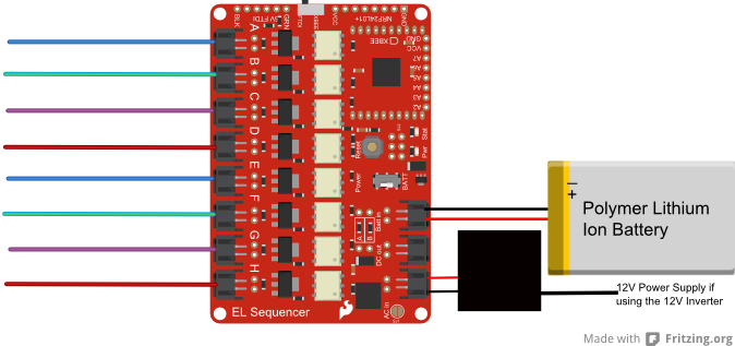
3V Inverter - If you are using the 3V inverter, you will need to hook up both wire pairs from the inverter to the Sequencer. The black/black wire pair will plug into the
AC InJST connector, while the red/black wire pair plugs into theDC OutJST connector.12V Inverter - While using the 12V inverter, there is only one wire pair that will plug into the Sequencer. The red/black wire pair will plug into the
AC InJST connector. You will need a separate power supply to run this inverter (such as the 12VDC 600mA Wall Adapter).
Connect the Power Supply
EL Sequencer
If you are using a battery for the power supply, you can connect this to the Batt In JST header without altering the board. Using an external power supply with the 3V inverter will require closing SJ1. You will need to connect that supply to the PTH headers labeled Batt In. Make sure the power supply falls in the range of 3.5V-16V for an external power supply.
EL Escudo Dos
The power supply for the EL Escudo Dos actually comes from the Arduino. We recommend using a 12V wall adapter for powering the Arduino.
Alternatively, if you would like to go wireless, you could use a male barrel jack adapter along with a 12V battery. Typically, however, the EL Sequencer will be a better option for you for wireless applications.
Final Circuit
Once everything is hooked up, your circuit should look something like the following: