Driving Motors with Arduino
 bri_huang
 Introduction
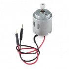
There are 20 GPIO (General Purpose Input \ Output) pins on the standard Arduino Uno and the SparkFun Redboard. These pins are limited to driving no more than about 40 mA of current. For controlling things like motors, 40 mA is just not enough. A small hobby motor requires at least 100 - 200 mA to spin up. To do this, we need to use a circuit called a transistor amplifier.
This project has been adapted from the Circuit #12 in the SparkFun Inventor's Kit (SIK) v3.3. We've updated the Fritzing diagrams and the code examples to make the connections easier to follow. The SparkFun Inventor's Kit is a great beginners kit to introduce you to the world of physical computing and Arduino.
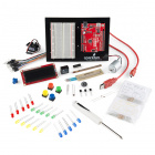
SparkFun Inventor's Kit - V3.3
KIT-13969Required Materials
We suggest that you start with a full SparkFun Inventor's Kit, but for this tutorial, we are going to be using the SparkFun RedBoard, but you can use any microcontroller development board you like including: Arduino, RedBoard, Photon or Teensy. The concepts covered here are universal to nearly all systems.
Hardware used in this tutorial:


Resistor 330 Ohm 1/6 Watt PTH - 20 pack
COM-11507These parts are all included in the standard SparkFun Inventor's Kit.
Suggested Reading
If you aren’t familiar with the following concepts, we recommend checking out these tutorials before continuing.
Voltage, Current, Resistance, and Ohm's Law
How to Use a Breadboard
What is an Arduino?
Transistors
Introducing the transistor
Before we jump in, let's take a look at the transistor. We will only briefly show how the transistor works in this application. If you're interested in learning more, we have a full tutorial on transistors here.
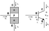
There are many different types of transistors; the one that we will be looking at is called an NPN BJT (Bi-Junction Transistor) transistor. The NPN describes the material properties of the device and how this devices behaves. (Note: There is also a PNP type transistor which works similarly but with different directions of current flow). A typical drawing or diagram of an NPN transistor looks like the image below.
Pin Labeling
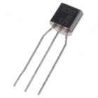
The three legs of the transistor are labeled Collector (C ), Base (B), and Emitter (E). Depending on the manufacturer and the package type, the order of these pins may differ. It's important to always double check the datasheets if you're not sure. There are two very common NPN transistors used with electronics. These are the 2N2222 and the BC337.
The pin labeling and orientation is the same for both the 2N2222 and the BC337. If you look at the top of a transistor, you'll notice that it has a shape of a capital letter D. There is one side that is curved and one side that is flat. Hold the transistor so that the pins are facing down and the flat edge faces to the left, the pins are in the same order as in the diagram above: Collector (top), Base (middle), and Emitter (bottom).
When looking at the schematic diagram for a transistor, the base is always in the middle; the emitter has an arrow pointing away (NPN transistors only), and the collector is the final un-marked pin.
How it works
Without going into too much depth on the nuances of semiconductors and quantum physics, here is a brief overview of how the NPN transistor functions. The transistor works like a switch. Imagine that there is a switch between the collector and the emitter. When the transistor is "off", the switch is open and current is not allowed to flow from the collector to the emitter. When the transistor is turned "on", the switch is closed and current flows from the collector to the emitter.
The base pin is used to control the transistor. When a voltage is applied to the base, the transistor turns on and current flows. The advantage of this configuration is that a low current signal from the Arduino can be used to turn the transistor on and off. The transistor works like a switch that can be used to close the circuit for a motor that is connected directly to the power supply.
Now, let's wire this up to our Arduino.
Wiring up the circuit
Here is the schematic diagram for the circuit that we are going to wire up:
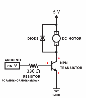
The transistor (switch) works in this circuit to close the circuit for the motor. One side of the motor is connected to 5V, the other is connected to the collector pin of the transistor, and the emitter is connected to ground. When a voltage is sensed at the base of the transistor, the transistor turns on, the switch is closed, closing the circuit for the motor circuit. Notice that the voltage for the motor comes directly from the 5V power supply.
Fly-back Diode
In this circuit, we also have a diode placed in parallel with the motor. Diodes only allow current to flow in one direction - as indicated by the arrow. This diode is often called a "fly-back" diode, and it helps to prevent damage to the transistor. As the motor starts and stops, the coils inside the motor can give create current spikes that may damage the transistor. This diode prevents that from happening.
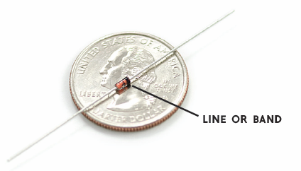
Most diodes have a line or a bar that marks one end of the device. This line corresponds the the line or bar on the end of the arrow in the diagram. In our circuit, this is connected to 5V.
Final circuit
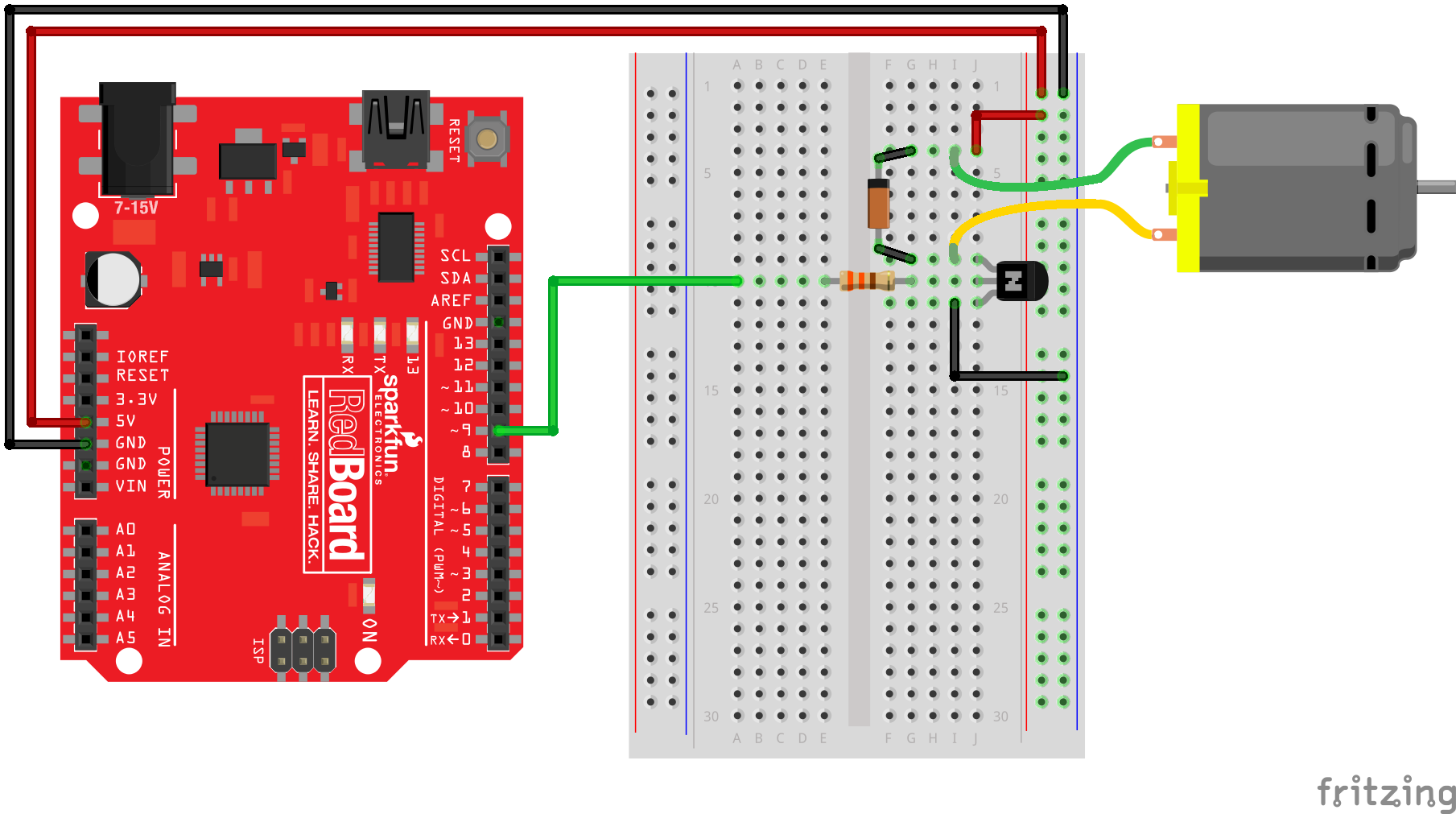
Here is the completed circuit as it should look like on your breadboard. Pay close attention to the direction of the diode. If it's plugged in backwards, you'll end up with unpredictable behavior. Notice that we are connecting one of the PWM pins (pin 9) on the Arduino to the base of the transistor. This will be our control signal for the motor.
Now you have your circuit, let's try out some sample code.
Example Code
With your transistor and motor connected up, let's try a few simple examples.
Motor Blink
This is the easiest example to try. This is essentially the blink example code. But, instead of blinking an LED on pin 13, we are setting pin 9 HIGH and LOW. We increased the delay to 5 seconds so that the motor isn't starting and stopping every second. Copy this code into Arduino and upload it to your board. You should see that the motor turns on for 5 seconds and then stops for 5 seconds. If it doesn't work, go back and double-check your wiring.
language:c
//Simple Motor Blink
//Turns pin 9 on and off repeatedly

void setup()
{
  pinMode(9, OUTPUT);
}

void loop()
{
  digitalWrite(9, HIGH);
  delay(5000);  //wait for 5 seconds
  digitalWrite(9, LOW);
  delay(5000);  //wait for 5 seconds
}
Serial Motor Speed Control
On and off are fun, but what about controlling the speed of the motor. We connected the transistor to pin 9 (a PWM pin) so that we can also use analogWrite() to control the speed of the motor. This is a little example sketch that allows you to type in values into the Serial Monitor to pass values to your program.
Copy this code into Arduino and upload it to your board. After the upload is complete, open up the Serial Monitor. Type in a value from 0 to 255 and hit enter. You should see the motor spin up. What's the slowest speed you can set this to? What happens when you put a load on the end of the motor? This is a great application for creating kinetic sculptures and moving things.
language:c
//Serial control of motor speed
//Upload this sketch and then open up the Serial Monitor. Type in a value (0 - 255) and hit enter.

int motorSpeed;

void setup()
{
  Serial.begin(9600);  //initiate Serial communication
  Serial.println("Type in a vale from 0 - 255 and hit enter.");
  pinMode(9, OUTPUT);
}

void loop()
{
  if (Serial.available() > 0)
  {
    motorSpeed = Serial.parseInt();
    Serial.print("Setting motor speed to: ");
    Serial.println(motorSpeed);
    analogWrite(9, motorSpeed);
  }
}
Can I change the direction?
The next thing you probably want to do is change or control the direction that the motor spins. Unfortunately, you can't do this with a single transistor. If you want to change the direction the motor spins, you can manually reverse the wires on the circuit, but there is no way to do this in code without introducing a new piece of hardware. To control speed and direction, you need 5 transistors arranged in a configuration called an H-Bridge.
In the diagram below, we have shown the transistors as simple switches. If we closed switch A and D, current flows through the motor from left to right. If we close switch B and C, current flows through the motor in the opposite direction from right to left.
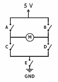
Check out the tutorial on getting started with the H-Bridge Robot.