Robot Quickstart!
 Miskatonic
Getting started
Introduction
How could you make a motor spin in different directions? With an H-Bridge! In this experiment you will use the H-Bridge to control the motor's direction and speed.
Parts Needed
You will need the following parts:
- 1x Breadboard
- 1x SparkFun RedBoard
- 1x TB6612FNG Motor Driver
- 2x Geared Motor
- 12x Jumper Wires
Suggested Reading
There is a dedicated hookup guide for the TB6612FNG driver, but this tutorial is designed to be a first glance. If you want a more in-depth look, you can read the hookup guide here:
Introducing the Hardware
Introducing the H-Bridge
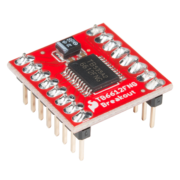
The Toshiba TB6612FNG is actually a dual H-bridge IC. This means it has two full H-bridge circuits built into a little package, allow- ing you to control the two motors on your robot with a single board. The H-bridge distinguishes the two motors as A and B, as you can see on the underside of the board in Figure 8-6. To control each H-bridge circuit, you use three signal wires: two for direction and one for speed. You can buy the board either with or without pins already sol- dered on, so if you want to save yourself the trouble of soldering, make sure you get the presoldered board (ROB-13845). If you have the board without header pins already soldered on (ROB-09457), it’s not a problem, but you’ll need to solder male headers onto the pins; for soldering instructions, see “How to Solder” on page 302. In either case, before you start building this project you should have a board that looks like first picture in this tutorial.
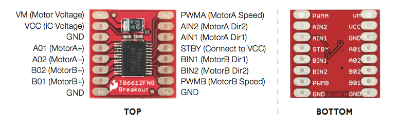
Hookup Table
| 1 | Motor voltage supply |
| 2 | Chip supply voltage |
| 3 | Ground 1 |
| 4 | AO1 motorA connection |
| 5 | AO2 motorA connection |
| 6 | BO2 motorB connection |
| 7 | BO1 motorB connection |
| 8 | Ground(GND) |
| 9 | Ground(GND) |
| 10 | PWMB (MotorB Speed) |
| 11 | BIN2(MotorB2 DIR2) |
| 12 | BIN2(MotorB2 DIR1) |
| 13 | STBY |
| 14 | AIN1(MotorA DIR1) |
| 15 | AIN2(MotorA DIR2) |
| 16 | PWMA (MotorA Speed) |
Geared Hobby Motor
The basic hobby motor is great for simple mechanisms like spinning fans, but it doesn’t offer a lot of torque (rotational force). In this project, we want to use a motor to move the entire project around, so we need to use a geared motor—a motor that’s attached to a gearbox.
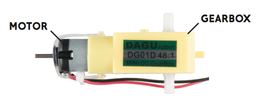
A gearbox essentially converts mechanical rotations into torque. This gearbox has a 48:1 gear reduction, which means 48 rotations of the motor equal one rotation of the output shaft. This slows down the motor by a factor of roughly 1/48 and results in a multiplication of the torque by a factor of 48. Basically, the output speed is slower, but the torque is a lot higher.
Hardware Hookup
Now, let’s wire this up to see how it all works. You’ll connect just one motor for now to test the H-bridge motor driver, so you’ll use only one half of the dual H-bridge board. Figure 8-9 shows how the board and Arduino should be wired. The board is split horizontally, with the top half controlling Motor A and the bottom half controlling Motor B, though the power pins are used for both motors. Connect 5 V and GND from the Arduino to the power rails on the breadboard, and make sure to add a jumper wire to connect the two 5 V rails of the breadboard so you can use either rail to give power; this will save you from crossing too many wires and keep your board neat.
| Polarized Components | Pay special attention to the component’s markings indicating how to place it on the breadboard. Polarized components can only be connected to a circuit in one direction. |
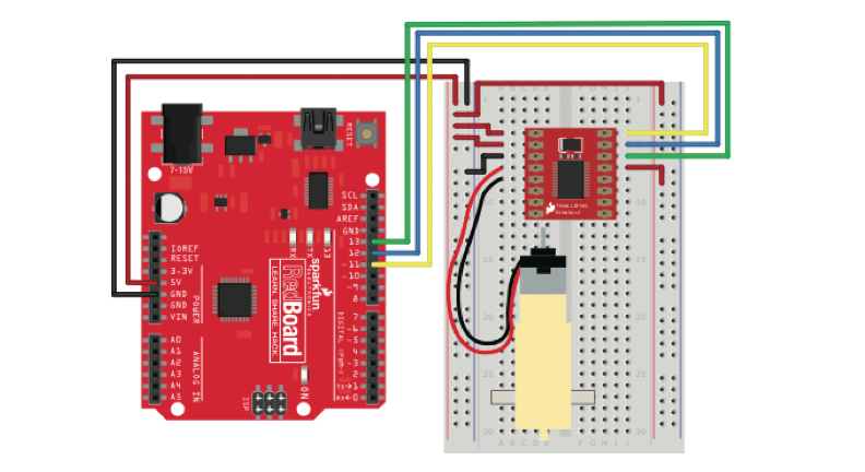
Starting from the top left of the H-bridge, connect 5 V to the top two pins, VM and VCC. VM controls the power for the motors, and VCC controls the power for the chip. Next, use a jumper wire to connect one of the chip’s GND pins to the GND rail of the breadboard. There are three pins available for ground on the H-bridge, as you can see in Figure 8-7, and you can use any of these. Next you’ll connect the motor. The motor has two wires: red and black. The orientation of the wires doesn’t actually matter, but for consistency connect the red wire to the pin labeled A01 and the black wire to pin A02. The remaining pins on the left side are those for controlling the second motor and another GND pin, so leave them for now. The pins on the top right of the H-bridge breakout board are for the signal wire connections for Motor A. The topmost pin, labeled PWMA, controls the motor’s speed. Connect this to pin 11 on the Arduino.
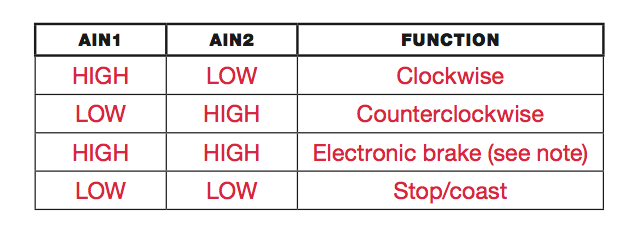
(Remember that pins 3, 5, 6, 9, 10, and 11 all have PWM capability and can be used with the analogWrite() function.) The next two pins, labeled AIN2 and AIN1, are used to control the direction and drive of Motor A, which you can do by setting these pins to different combinations of HIGH and LOW. Table 8-1 shows the combinations. Connect AIN2 to Arduino pin 12 and AIN1 to Arduino pin 11.
Lastly you’ll need to disable the STBY pin. As mentioned earlier, this H-bridge IC has a standby pin that allows you to put the chip into a low-power sleep mode, which is useful for applications where power consumption is a concern. For this project, you don’t need this feature, so you’ll disable it. This chip is designed with STBY as an active low input. This means that when this pin is LOW, it goes into standby mode. To disable standby, you’ll connect this pin directly to 5 V on the power rail.
Programming the 'Bot
PROGRAM THE BOT
Let’s start the sketch with a little test. This simple example will spin the motor clockwise slowly for 1 second, change directions and spin counterclockwise quickly for 1 second, and then stop for 1 second before starting again. Open the Arduino IDE, and copy the code in Listing 8-1 into your window. When you’re done, click Upload and watch what happens!
Open the Sketch
Open the Arduino IDE software on your computer. Coding in the Arduino language will control your circuit.
You can type out or copy and paste the following code into the Arduino IDE. Hit upload, and see what happens!
language:cpp
const byte AIN1 = 13;
const byte AIN2 = 12;
const byte PWMA = 11;

void setup()
{
 pinMode(AIN1, OUTPUT);
 pinMode(AIN2, OUTPUT);
 pinMode(PWMA, OUTPUT);
 }

void loop() {
  //set direction to clockwise
  digitalWrite(AIN1, HIGH);
  digitalWrite(AIN2, LOW);
  analogWrite(PWMA, 50);
  delay(1000);

  //set direction to counterclockwise
  digitalWrite(AIN1, LOW);
  digitalWrite(AIN2, HIGH);
  analogWrite(PWMA,  255);
  delay(1000);

  //brake
  digitalWrite(AIN1, HIGH);
  digitalWrite(AIN2, HIGH);
  delay(1000);
}
The sketch starts with a new data type: const byte . The keyword const is used to declare a constant, which is like a variable but with a value that can’t be changed again later in the code. Thus, constants are useful for declaring things that will stay the same throughout the code, like pin numbers or configurations.
In this case, these constants define the pin numbers that control the H-bridge. Since the pin numbers are numbers between 0 and 13, you can define these constants as the data type byte. Next, you set the pins as outputs, and then set the direction you want the motor to spin using two digitalWrite() functions on pins AIN1 and AIN2. The first loop block sets AIN1 to HIGH and AIN2 to LOW, which spins the motor clockwise. To set the speed, you use an analogWrite() function on the PWMA pin. You may recall from Project 5 that you can use analogWrite() to set an analog pin to a PWM value from 0 to 255; the value given here, 50, is relatively slow. The motor will spin for 1 second because of delay(1000), and the next loop block changes directions with two more digitalWrite() functions. Here the sketch simply swaps which pin is HIGH and which is LOW, sets the speed to 255 with analogWrite(), and adds another delay(1000) to set it to spin for 1 second. The last part of the sketch sets both AIN1 and AIN2 to HIGH y, with another delay(1000). This applies an electronic brake and stops the motor for 1 second before the loop begins again and repeats the pattern.
Using this code as an example, you can now control both the speed and direction of a motor with just three lines of code! But we can make this even simpler. Let’s clean up the code by using custom functions.
Create a Custom Function
At the moment, every time you want to control the motor you’re using three lines of code: two to control the direction and one to set the speed. In this section you’ll make a custom function that will take just one number to determine both the direction and the speed of the spin. This number can be anything between -255 and 255 and will spin the motor clockwise if the number is positive and counter- clockwise if it’s negative. Add the code below to the very end of your sketch.
language:cpp
void setMotorA(int motorSpeed)
{
if (motorSpeed > 0)
     {
       digitalWrite(AIN1, HIGH);
       digitalWrite(AIN2, LOW);
      }
else if (motorSpeed < 0)
     {
       digitalWrite(AIN1, LOW);
       digitalWrite(AIN2, HIGH);
      }
else {
       digitalWrite(AIN1, HIGH);
       digitalWrite(AIN2, HIGH);
     }
analogWrite(PWMA, abs(motorSpeed));
}
Name the function setMotorA(). This function uses a number as a single argument named motorSpeed to set the motor’s speed. First, a simple if() statement determines whether the number is positive or negative by checking whether motorSpeed is greater or less than zero. If motorSpeed is positive, the if() statement sets the direction pins so that the motor spins clockwise. If it’s negative, an else if() statement sets the direction pins to spin the motor counterclockwise. If it’s neither positive nor negative (that is, if it’s 0), a final else statement sets both direction pins HIGH to apply the brake and stop the motor. The second else statement has a line that uses the abs() mathematical function to find the absolute value of motorSpeed. The analogWrite() function sets the speed of the motor, but it works only with values from 0 to 255. The abs() function makes sure that the positive part, or absolute magnitude, of motorSpeed is used to set the speed.
Clean Up the Code
Now, let’s clean up the loop() with this new function. You can see in code below that the loop() code is much shorter and easier to read. Make these changes to the loop() in your sketch and upload it to your board. It should behave the same way as before. Now, if you want to set the motor to a different speed or direction, you can do it with just a single line of code!
language:cpp

void loop() {
  //set direction to clockwise
  setMotorA(100);
  delay(1000);
  //set direction to counterclockwise
  setMotorA(-255);
  delay(1000);
  //stop
  setMotorA(0);
  delay(1000);
}
This code sets a setMotorA() value and a delay to make each change in speed and direction. Now you have the beginnings of your Drawbot! Next, you’ll wire the second motor.
WIRE THE SECOND MOTOR
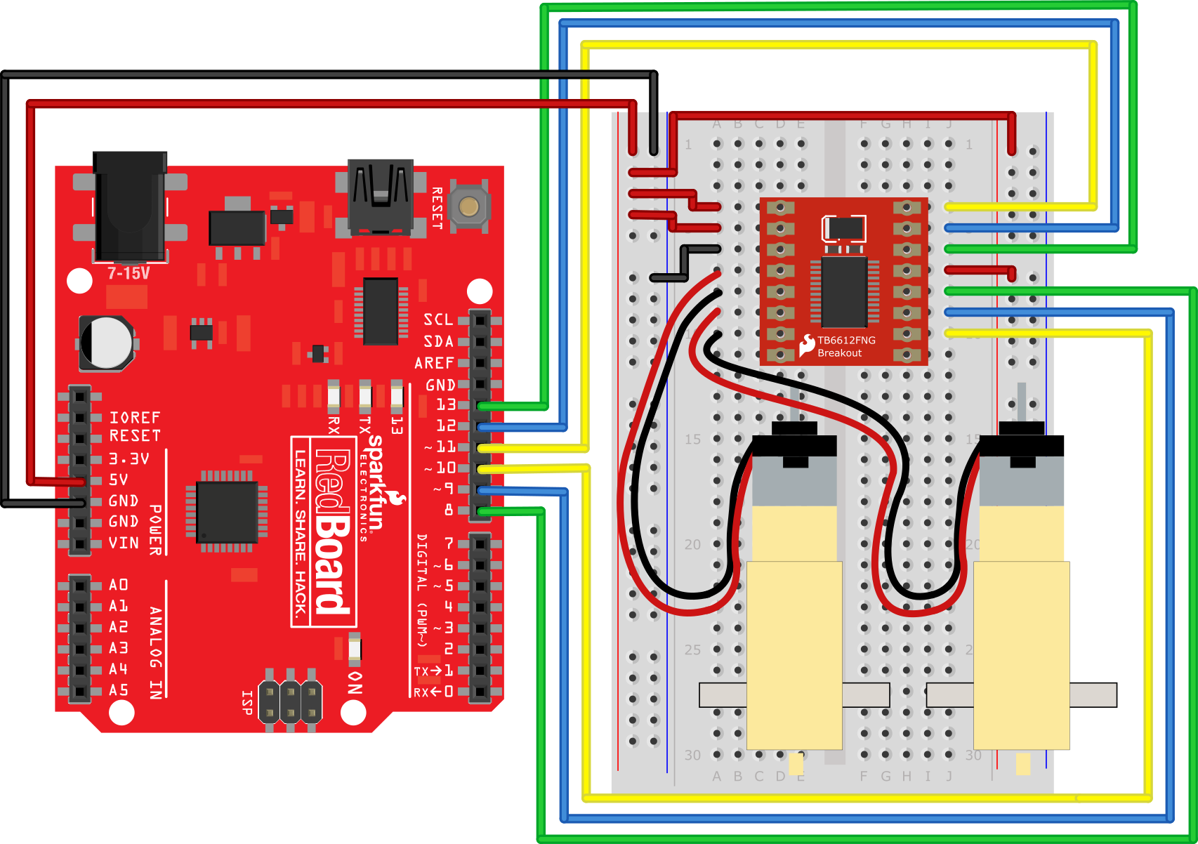
The Bot needs a second motor so it can zip around on two wheels. Figure 8-10 shows how the second motor will be wired. Plug Motor B in on the left side of the breakout board just below the connections for the first motor, with the red wire connected to B02 and the black wire connected to B01. Next, add the signal control lines to the H-bridge breakout board, just below the STBY pin on the right side. Connect the PWMB pin on the H-bridge to Arduino pin 10 for speed control, and connect the BIN1 and BIN2 pins to Arduino pins 8 and 9, respectively, for direction control.
Add code to control the second motor
First, the declarations and then the setup portions
language:cpp
const byte AIN1 = 13;
const byte AIN2 = 12;
const byte PWMA = 11;

const byte BIN1 = 8;
const byte BIN2 = 9;
const byte PWMB = 10;

void setup()
{
pinMode(AIN1, OUTPUT);
pinMode(AIN2, OUTPUT);
pinMode(PWMA, OUTPUT);
pinMode(BIN1, OUTPUT);
pinMode(BIN2, OUTPUT);
pinMode(PWMB, OUTPUT);
}
This code adds the three additional constants for the signal control pins for Motor B, and sets each of these pins as OUTPUT in the setup(). Next, you’ll again write a custom function to control Motor B. This code is so similar to the setMotorA() function that you can save yourself some typing by highlighting the code for setMotorA(), copying it (ctrl-C), pasting it (ctrl-V) below the setMotorA() function, and changing the As to Bs. This is a technique that programmers use a lot, and it can save you a lot of time. You just need to make sure you’re careful to change all the As to Bs in this second custom function or the code won’t work.
language:cpp
void setMotorB(int motorSpeed)
{
  if (motorSpeed > 0)
  {
    digitalWrite(BIN1, HIGH);
    digitalWrite(BIN2, LOW);
  }
  else if (motorSpeed < 0)
  {
    digitalWrite(BIN1, LOW);
    digitalWrite(BIN2, HIGH);
  }
  else
  {
    digitalWrite(BIN1, LOW);
    digitalWrite(BIN2, LOW);
  }
  analogWrite(PWMB, abs(motorSpeed));
}
The sketch will now need motorSpeed values for both setMotorA() and setMotorB(). Let’s add those to test the motors out together.
DRIVE BOTH MOTORS
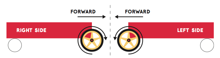
To make your bot drive forward, you’ll need the right motor to spin clockwise and the left motor to spin counterclockwise. This may seem counterintuitive, but take a look at a robot base from the side. The picture below shows a robot frame from both sides with arrows indicating the forward direction.
 <-
<-
On the right side of the robot, the wheel needs to spin clockwise for the robot to move forward, but on the left side of the robot, the wheel needs to spin counterclockwise. Pay attention to the direction in which each axle is spinning. If you need to, attach a piece of masking tape to the spinning end of the motor so that you can see the axle’s direction. Now, to make the robot go backward, you just reverse those directions. After adding the custom function code for setMotorB() to your sketch, adjust your loop() to look like the code below, and then upload this code and watch your motors spin!
    language:cpp
    ///////
    void loop() {
      //drive forward medium speed for one second
      setMotorA(100);
      setMotorB(-100);
      delay(1000)

      //drive backward quickly for one second
      setMotorA(-255);
      setMotorB(255);
      delay(1000);

      //stop for one second
      setMotorA(0);
      setMotorB(0);
      delay(1000);
    }
New loop() code to test both motors
Now, to make the robot go backward, you just reverse those directions. After adding the custom function code for setMotorB() to your sketch, adjust your loop() to look like Listing 8-6, and then upload this code and watch your motors spin!
You should see that Motor A (right side) is spinning clockwise and Motor B (left side) is spinning counterclockwise, and then after 1 second they flip. If you find that the motors are spinning in the same direction, swap the red and black wire connections on one of the motors. With just a few lines of code, you can make your bot move forward, turn right, turn left, move backward, and jiggle around!
Now it’s time to build a frame or a chassis for your bot. Because the code you wrote is all in the loop() part of the sketch, your motors will continue to spin, stop, spin, and stop. To stop the motors from spinning while you’re building the chassis for your bot, temporarily disconnect the USB cable from your computer.
Complete Code
Here's the complete test code. We've created two custom functions to control the two motors: setMotorA() and setMotorB(). These functions take a single parameter from -255 to +255 that defines the speed of the motor. Positive values drive the motor clockwise, and negative values drive the motor counter-clockwise.
language:cpp
const byte AIN1 = 13;
const byte AIN2 = 12;
const byte PWMA = 11;

const byte BIN1 = 8;
const byte BIN2 = 9;
const byte PWMB = 10;

void setup()
{
  pinMode(AIN1, OUTPUT);
  pinMode(AIN2, OUTPUT);
  pinMode(PWMA, OUTPUT);
  pinMode(BIN1, OUTPUT);
  pinMode(BIN2, OUTPUT);
  pinMode(PWMB, OUTPUT);
}

void loop()
{
  //set direction to clockwise
  setMotorA(50);
  setMotorB(-50);
  delay(1000);

  //set direction to counterclockwise
  setMotorA(-255);
  setMotorB(255);
  delay(1000); //brake

  setMotorA(0);
  setMotorB(0);
  delay(1000);
}

void setMotorA(int motorSpeed)
{
  if (motorSpeed > 0)
  {
    digitalWrite(AIN1, HIGH);
    digitalWrite(AIN2, LOW);
  }
  else if (motorSpeed < 0)
  {
    digitalWrite(AIN1, LOW);
    digitalWrite(AIN2, HIGH);
  }
  else
  {
    digitalWrite(AIN1, HIGH);
    digitalWrite(AIN2, HIGH);
  }
  analogWrite(PWMA, abs(motorSpeed));
}

void setMotorB(int motorSpeed)
{
  if (motorSpeed > 0)
  {
    digitalWrite(BIN1, HIGH);
    digitalWrite(BIN2, LOW);
  }
  else if (motorSpeed < 0)
  {
    digitalWrite(BIN1, LOW);
    digitalWrite(BIN2, HIGH);
  }
  else
  {
    digitalWrite(BIN1, HIGH);
    digitalWrite(BIN2, HIGH);
  }
  analogWrite(PWMB, abs(motorSpeed));
}
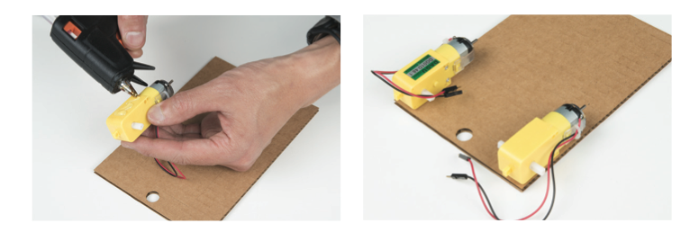
Building your bot
Using tape or a hot glue gun, attach the motors to the under- side of the chassis, oriented as shown in the photo below, with the motor hub near the back and the longer end of the motor body toward the front. (Hot glue is a great semipermanent method for attaching things because you can simply scrape it away with a craft knife and remove the part if you want to reuse it later.) You may need to temporarily disconnect the motors from your breadboard circuit while you’re attaching them to the chassis, so just remember to reconnect them to the circuit after you’ve glued them down. Refer back to the diagrams above if you need help rewiring it.