Discrete Semiconductor Kit Identification Guide
 Byron J.
 Overview
Let's start with a couple of definitions.
1. Separate; distinct; individual; non-continuous.
2. That can be perceived individually and not as connected to, or part of something else.
3. (electrical engineering) Having separate electronic components, such as individual resistors and inductors — the opposite of integrated circuitry.
1. Respectful of privacy or secrecy; quiet; diplomatic.
2. Not drawing attention, anger or challenge; inconspicuous.
Usage notes
Courtesy Wiktionary.org
Background
If you do anything with electronics, you're probably already using transistors, but you're probably using them in large, highly-integrated clusters. For example, the ATMega328P (the main chip on the RedBoard and ProMini) contains hundreds of thousands of them. They're tiny, encaplsulated in plastic, and already configured to be used as a microcontroller.
But sometimes you only need one...and if you don't have one handy, it can be inconvenient to have to go and order a single transistor.
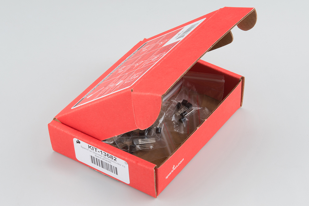
The Discrete Semiconductor Kit addresses your basic discrete semiconduictor needs. It's got PNP and NPN bipolar transistors, N-channel and P-channel MOSFETs, diodes, adjustable voltage references, and adjustable voltage regulators.
This guide will walk you through identifying each of these components.
Background Materials
- Our Transistor Tutorial covers the basics of bipolar junction transistors.
- There are According To Pete episodes in which he discusses:
- All of the components in this kit are polarized.
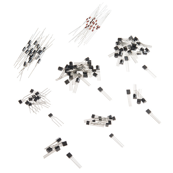
Kit Contents
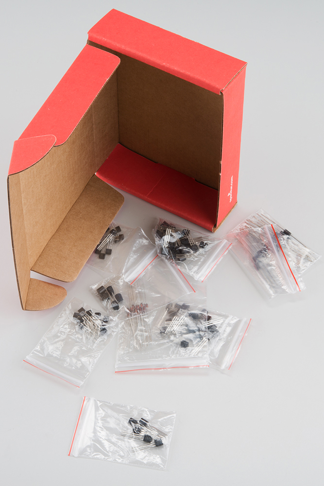
List of contents
You will find the following parts in the kit.
| Discrete Semiconductor Kit Bill Of Materials | |||||
| Quantity | Part Number & Link toDatasheet | Type | Marking | ||
| 25 | 2N3904 | NPN Transistor | 2N3904 | ||
| 25 | 2N3906 | PNP Transistor | 2N3906 | ||
| 10 | 5LN01SP | N-channel MOSFET | YB | ||
| 10 | 5LP01SP | P-Channel MOSFET | XB | ||
| 20 | 1N4148 | Silicon Diode | 4148 | ||
| 20 | 1N4004 | Power Diode | 1n4004 | ||
| 5 | TL431A | Voltage Reference | TL431A | ||
| 5 | LM317L | Voltage Regulator | LM317LZ | ||
A lot of these parts look very similar. The "marking" column above indicates the designation that you'll find printed in the part itself. With the exception of the MOSFETs, the marking usually contains a version of the part number. Some parts may also have additional symbols or printing, indicating things like the manufacturer and date of production.
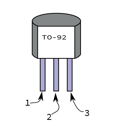
The BJTs, voltage references and regulators are all the common TO-92 form factor, with a body about the size of a pencil eraser, and three protruding legs. The MOSFETs are the slightly smaller SC-72 (AKA "Single SPA") package.
The polarity of these devices is important, and usually referenced by pin number.
To identify the pins, hold the device so that the marking side is factng you, and the legs are pointing downwards. From left to right, the pins are numbered 1, 2 and 3. The function assigned to each pin depends on the device, and we'll cover that for each part in its respective section.
Specifications
Because discrete semiconductors are a basic building block of electronic circuits, they have much more detailed specifications than other components. A critical parameter in one application might be nonsensical in another. This makes it hard to present an abbreviated synopsis of part specs. Rather than listing some parameters inline, we've instead decided to make it easy to access the parametric information, by linking the part numbers in the table above table to the corresponding datasheets.
Diodes
The diodes are the simplest semiconductors in the kit, each with two leads. They are both silicon diodes, generally similar, but with different maximum voltage and current specs.
Power Diodes
The 1N4004 power diodes are black cylinders with grey markings, and they're larger than the small signal diodes. There are 20 of them in the kit. The marking "1N4004" is printed on the body.
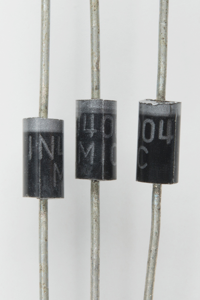
Since these are power diodes, they can withstand high voltage and current. They are rated to 400V maximum reverse voltage, and and average rectified current output of 1A. The forward voltage required to turn them on is a touch high, at a maximum of 1 Volt. Casual testing of the forward drop on the workbench revealed the actual forward voltage to be somewhat lower, around 0.7 V.
Power diodes are typically used as bridge rectifiers in power supplies.
Small Signal Diodes
There are also 20 pieces of the 1N4148 small signal diode. It is smaller than the power diodes, with an orange glass body, again with a stripe at one end.

"4148" is printed on the body of the diode, but because the body is clear, the number can be hard to see.
These diodes are suited for applications that don't require high voltage or current. They're rated to 100V maximum reverse voltage, and average forward current of 200 mA. Like the power diodes, the stated max forward voltage is 1V, but typically measures closer to 0.65V. Typical applications include diode logic or precision rectifiers.
Diode Polarity
The polarity of both diodes is indicated with a stripe on one end of the body. The stripe corresponds to the line in the schematic symbol, indicating the cathode. The other end (no stripe) is the anode, indicated by the triangle in the schematic symbol.
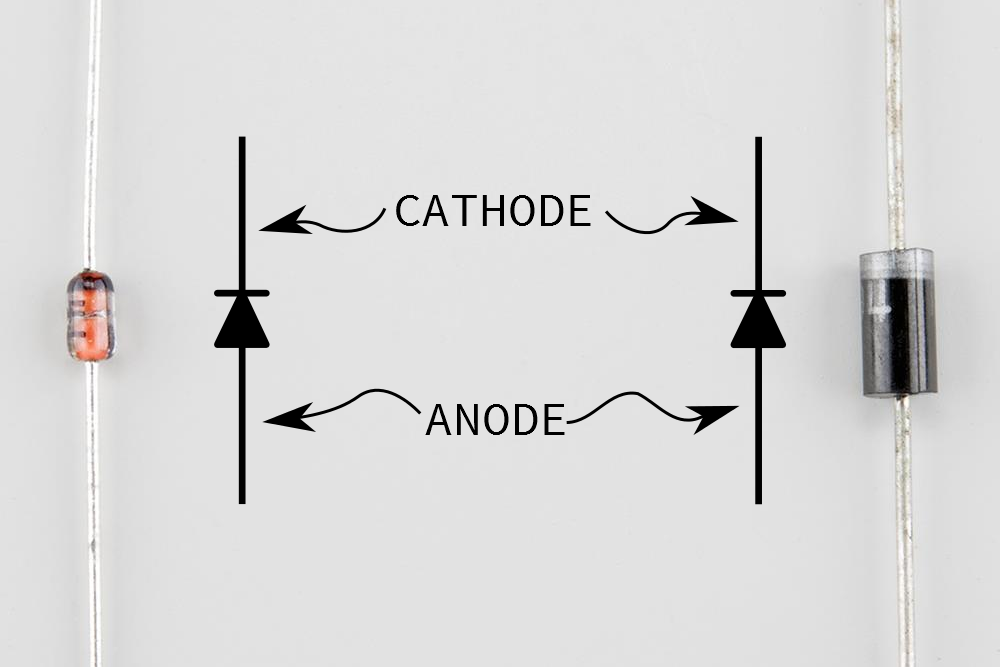
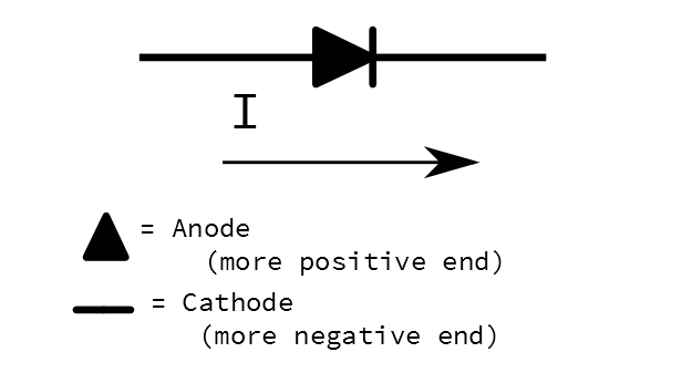
Once the forward voltage is exceeded, current flows through a diode from anode to cathode. This leads us to some mnemonic devices for remembering with terminal is which.
- The line in the schematic symbol, and printed on the body, is the cathode. The line a similar to a minus sign, because this will be the more negative end of the diode.
- The triangle in the schematic symbol is the Anode, the letter "A" makes a triangle.
- The triangle in the symbol also matches the arrowhead we draw to represent current flow.
Transistors
Biploar Junction Transistors
The ordinary transistor is the Bipolar Junction Transistor. Electrical engineers often abbreviate the name to the initialism "BJT." This kit contains 25 pieces each of the 2n3904 and 2n3906 BJTs. These are ubiquitous "jellybean" parts, usable for many general purpose transistor circuits.
If you look in a book of basic transistor circuits, there's a good chance you will run across the 2N3904 and its complement, the 2N3906. They have been in production for a long time, and are very useful generic transistors.
2N3904 NPN
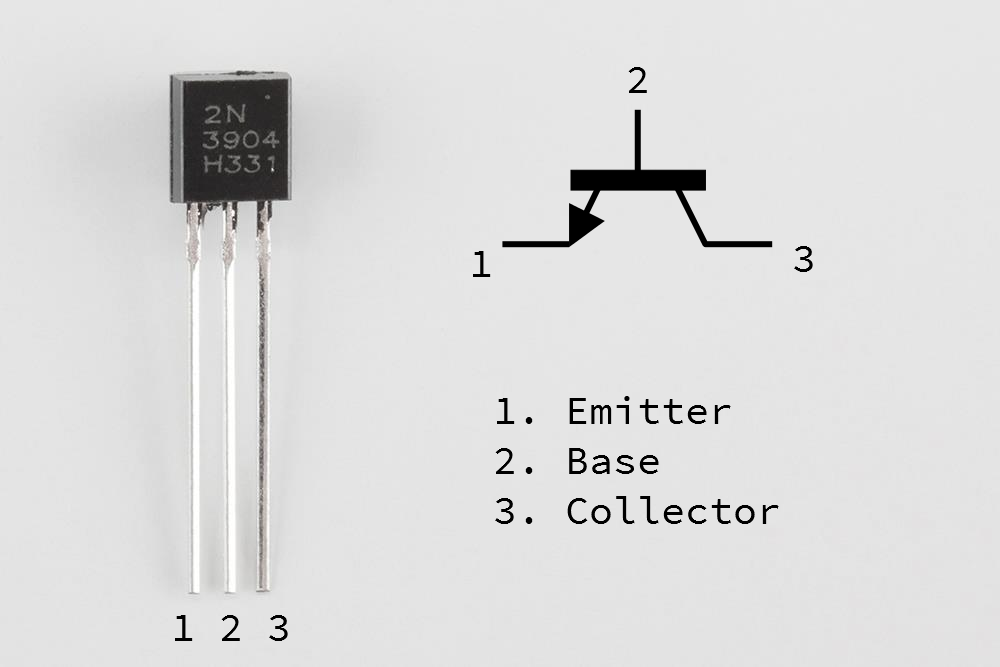
The pinout is fairly straightforward:
- Emitter
- Base
- Collector
2N3904s are easy to use on the breadboard, because the base is in the middle -- the schematic symbol and the part itself correspond.
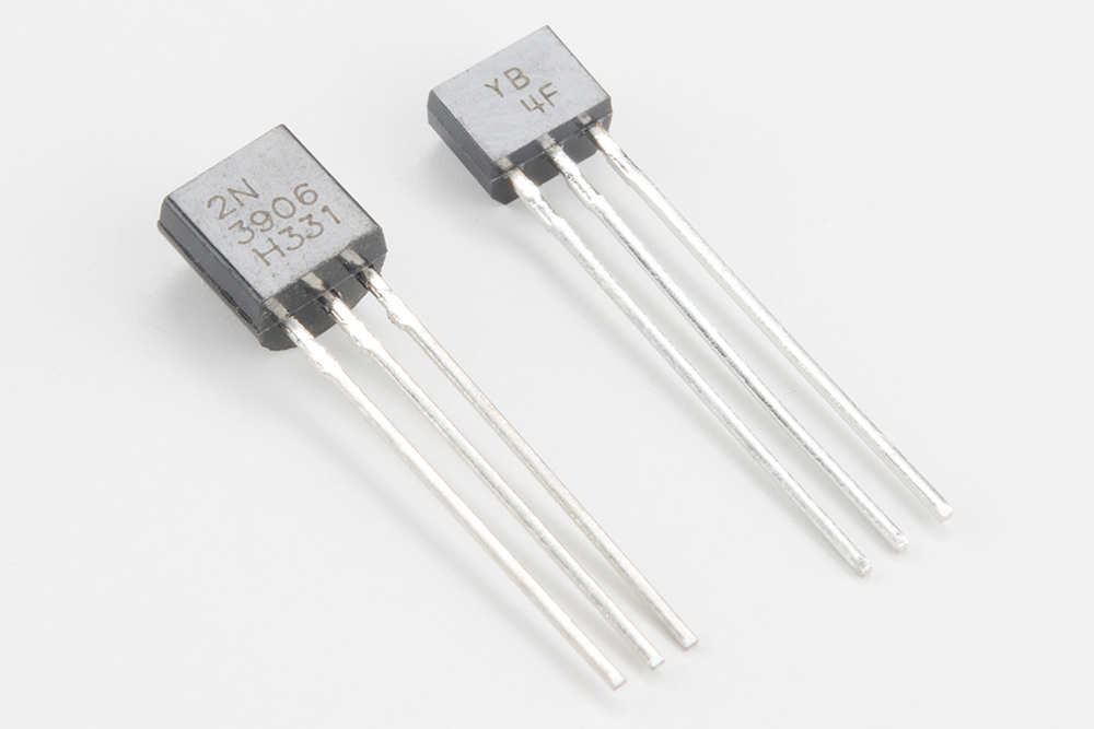
2N3906 PNP
The 2N3906 is the PNP complement of the 2N3904.

The pin order 2N3904 and 2N3906 is easy to remember because they're the same. Just memorize the letters "EBC."
Even though the pins are in the same order, keep in mind that the emitter flips around between the NPN and PNP variants! You can consider the 2N3906 as the mirror-image of the 2N3904.
MOSFETs
The MOSFETs in the kit are smaller than the other transistors - the body is about half the size. Being smaller, there's less room to print on them, so the part numbers are a terse code.
5LN01SP N-Channel MOSFET
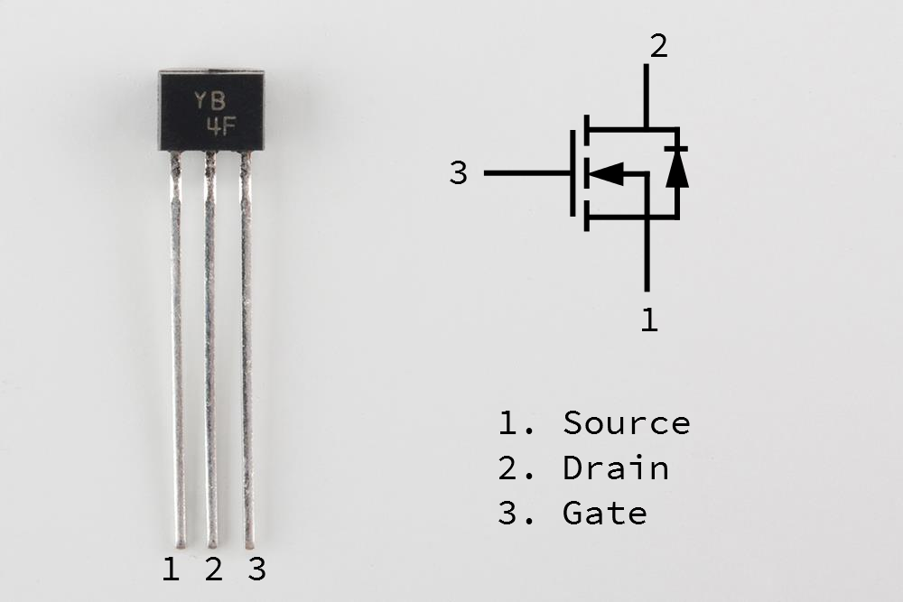
The letters "YB" on the package are the identifier. The other marking on the part in the photo is a lot number or date code, which isn't particularly meaningful if you don't know how to decode it.
The pinout is
- Source
- Drain
- Gate
5LP01SP P-Channel MOSFET
Due to the underlying semiconductor physics involved, P-channel MOSFETs are less common than N-channel. The 5Lx01SP family is somewhat unique in that it includes a P-channel variant, which is a reasonable complement for its N-channel sibling.
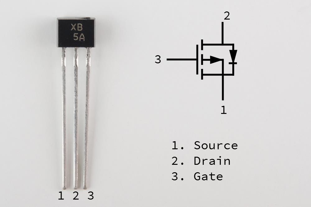
Again, the markings on the part are somewhat cryptic -- the "XB" printed on the body is the identifier.
The pinout matches its N-channel cousin (source, gate, drain). Like the BJTs, these MOSFETs have the same pinout, but the polarity is reversed.
While the 5LP01SP is intended as a complement for the 5LN01SP, its specs aren't a perfect mirror-image. Its transconductance is lower, gate capacitance is higher, and switching time slower. These differences may not be significant in typical applications.
Voltage Devices
We're actually cheating the definition of discrete a little bit with the next two components. They're both actually integrated circuits!
They're still in TO-92 packages, though. The first is actually a general purpose replacement for Zener diodes. The second is a voltage regulator -- again, not discrete, but very handy to have around.
TL431A Voltage Reference
When we were selecting parts for this kit, we thought it might be nice to have some Zener diodes -- but there was no agreement as to the Zener voltage. What we really wanted was an adjustable Zener Diode: enter the TL431A voltage reference. It functions similarly to a Zener diode, but the voltage is set using external resistors.

The output voltage can be varied between 2.5V and the power supply voltage, up to 36V. Like a Zener Shunt, it requires a resistor in series with the cathode.
Zener shunt circuits are useful when you want to generate a stable and constant voltage but the input voltage varies. For instance, the RedBoard can accept between 7 and 15VDC on its barrel jack. If we need to derive a stable reference voltage from that, that most obvious approach would be to use a voltage divider, but we'd find that the resulting voltage would vary in relation to the input voltage. A Zener shunt (or active voltage reference) is a way of deriving an input-independent reference voltage.
Polarity
The TL431A has three terminals, the reference voltage, anode, and cathode. The anode and cathode terminology is borrowed from Zener diodes.
This will make more sense as we explore the following examples.
Sample Circuits
The simplest TL431A circuit requires a single resistor on the cathode. The reference pin is tied to the cathode, and the output is taken from the cathode. The result is 2.5V at the cathode, regardless of the input voltage.
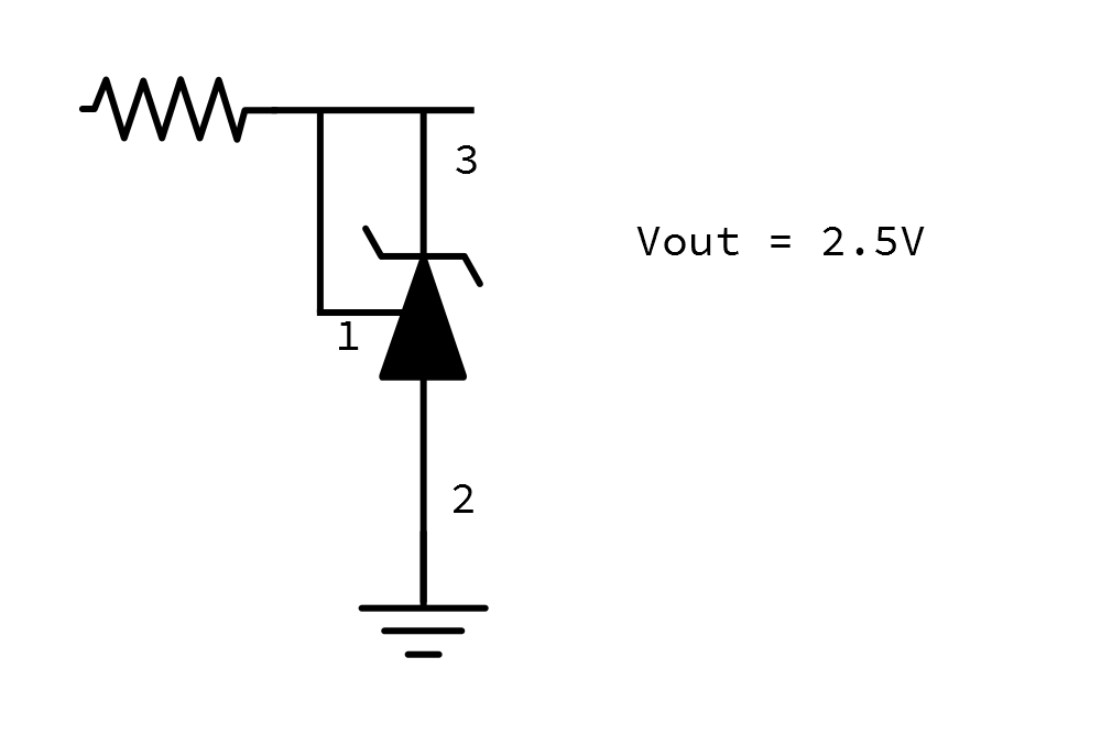
The input resistor shown in the diagram above needs to be selected to bias the TL431A with at least 1 mA. You can find a maximal value using the formula Rin = (Vin-Vout)/0.001. Typical applications use values between 150 Ω and 10KΩ For use as an unloaded voltage reference, the input resistor is relatively noncritical, though if significant current is being supplied, a smaller resistor will dissipate less power.
Varying the output voltage requires two more resistors.
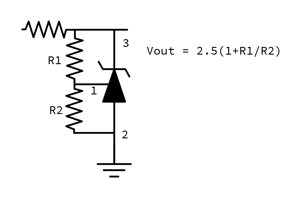
You can make a variable voltage reference if you use a potentiometer for R1, as shown in Figure 10 of the datasheet.
The output of the TL431A is best suited as a reference for other circuitry (such as comparators or analog-to-digital converters), and not particularly suited for powering external circuitry. While it creates a stable output voltage, it requires the cathode resistor, which will dissipate heat if the load draws very much current. The adjustable voltage regulator is a similar integrated circuit that bypasses this limitation.
LM317L Voltage Regulator
The LM317L is similar to the TL431A, but it's intended to be used as part of a power supply.
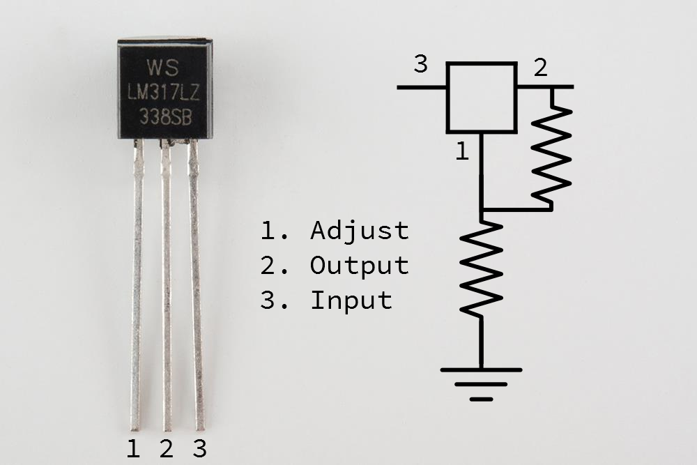
You'll notice the marking on the part in the photo has an extra suffix of "Z", which indicates a TO-92 body, packaged as loose pieces (as opposed to on tape).
The configuration of the LM317L is also similar to the LT431A, with a pair of resistors setting the output voltage. You'll notice that it doesn't require a resistor on the input like the TL431A did.
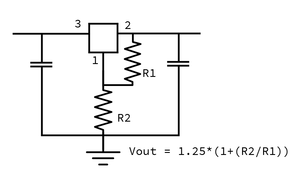
In this circuit, it's worth noting the capacitors from the input to ground and the output to ground. The datasheet states
An input capacitor is not required, but it is recommended, particularly if the regulator is not in close proximity to the power-supply filter capacitors.
...
An output capacitor improves transient response, but it not needed for stability.
It goes on to recommend values of 0.1uF for the input capacitor, and 1uF for the output.
The LM317L is rated to supply up to 100 mA. If you need more current, consider stepping up the the LM317L's larger brother, the TO-220-cased LM317. If you add a large heatsink, you can draw significantly more current from it.
Resources and Going Further
Resources
- Datasheets for each device:
- Here are a couple of handy online calculators
- For LM317 resistors
- For TL431A resistors
- Those funny 1Nxxxx and 2Nxxxx part numbers are examples of the JEDEC numbering system.
Going Further
- If you're building circuits with discrete semiconductors, you'll likely need some other components to get the most out of them.
- There are many Accoding to Pete videos discussing applications of discrete semiconductors.
- Forrest Mims' books are full of simple circuits you can build on a breadboard with a handful of components. Of particular relevance to discrete semiconductors are the circuits in Electronic Formulas, Symbols & Circuits.
- For a little more advanced project, Hi-fi audio guru Nelson Pass wrote a great article on building discrete OpAmps, using bipolar transistors, MOSFETs and vacuum tubes.