Discrete Semiconductor Kit Identification Guide
 Byron J.
Diodes
The diodes are the simplest semiconductors in the kit, each with two leads. They are both silicon diodes, generally similar, but with different maximum voltage and current specs.
Power Diodes
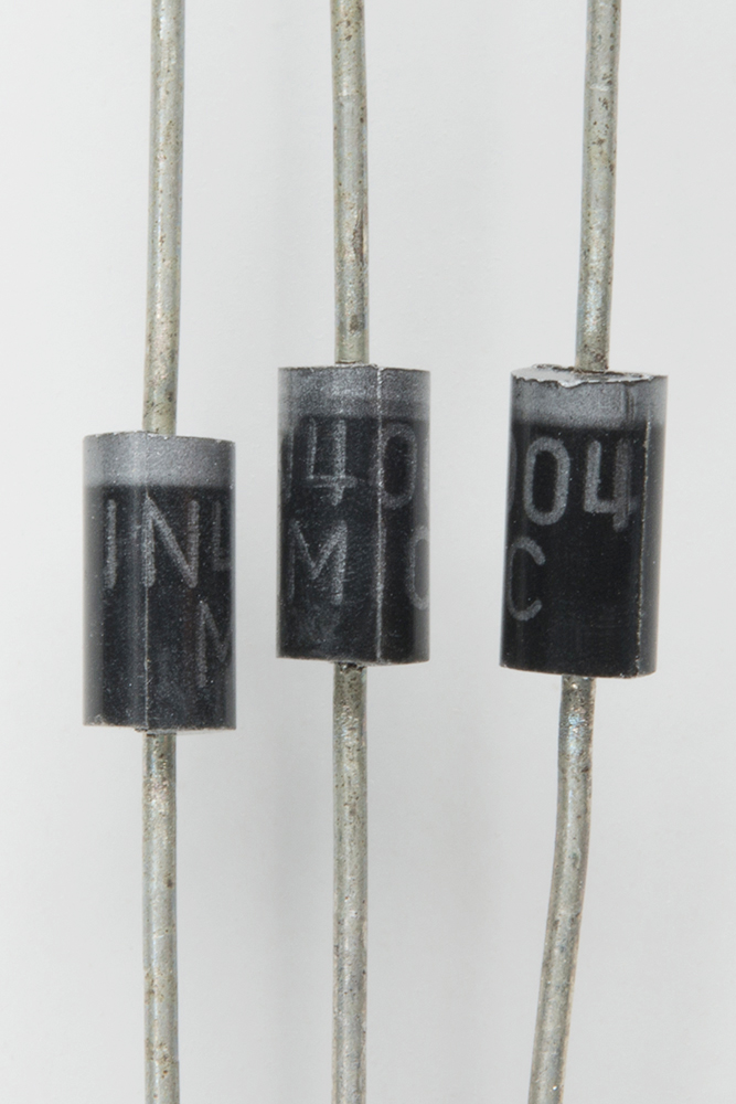
The 1N4004 power diodes are black cylinders with grey markings, and they're larger than the small signal diodes. There are 20 of them in the kit. The marking "1N4004" is printed on the body.
Since these are power diodes, they can withstand high voltage and current. They are rated to 400V maximum reverse voltage, and and average rectified current output of 1A. The forward voltage required to turn them on is a touch high, at a maximum of 1 Volt. Casual testing of the forward drop on the workbench revealed the actual forward voltage to be somewhat lower, around 0.7 V.
Power diodes are typically used as bridge rectifiers in power supplies.
Small Signal Diodes
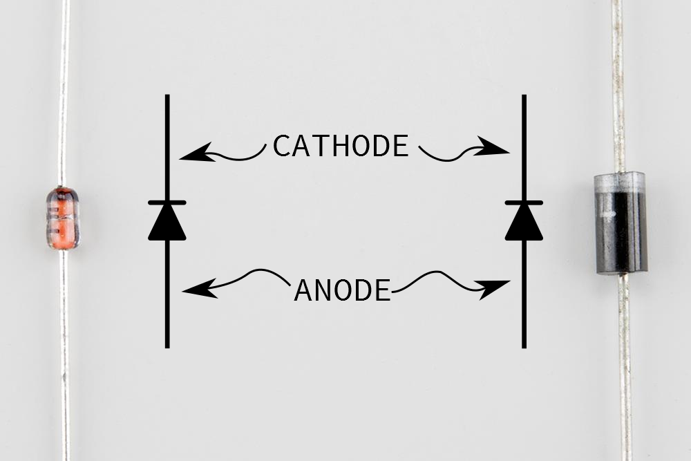
There are also 20 pieces of the 1N4148 small signal diode. It is smaller than the power diodes, with an orange glass body, again with a stripe at one end.

"4148" is printed on the body of the diode, but because the body is clear, the number can be hard to see.
These diodes are suited for applications that don't require high voltage or current. They're rated to 100V maximum reverse voltage, and average forward current of 200 mA. Like the power diodes, the stated max forward voltage is 1V, but typically measures closer to 0.65V. Typical applications include diode logic or precision rectifiers.
Diode Polarity
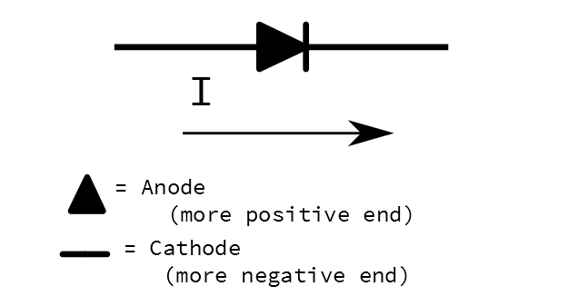
The polarity of both diodes is indicated with a stripe on one end of the body. The stripe corresponds to the line in the schematic symbol, indicating the cathode. The other end (no stripe) is the anode, indicated by the triangle in the schematic symbol.
Once the forward voltage is exceeded, current flows through a diode from anode to cathode. This leads us to some mnemonic devices for remembering with terminal is which.
- The line in the schematic symbol, and printed on the body, is the cathode. The line a similar to a minus sign, because this will be the more negative end of the diode.
- The triangle in the schematic symbol is the Anode, the letter "A" makes a triangle.
- The triangle in the symbol also matches the arrowhead we draw to represent current flow.