Cherry MX Switch Breakout Hookup Guide
 jimblom
 Introduction
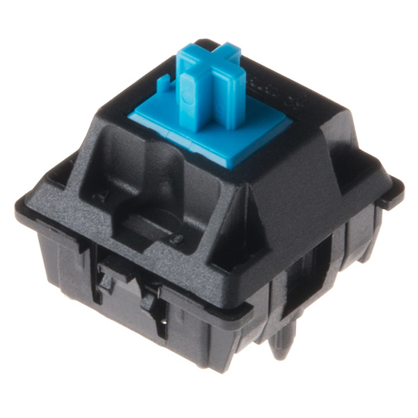
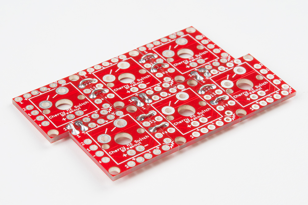
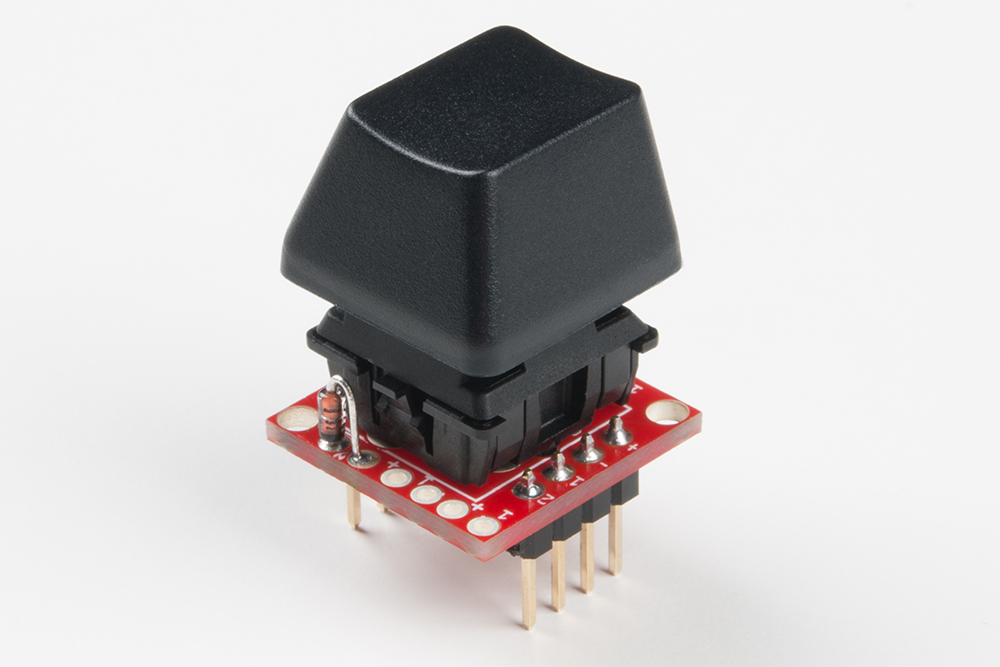
Cherry MX Keyswitches are top-of-the-line mechanical keyboard switches. They're satisfyingly "clicky", reliable up to tens-of-millions of key presses, and an essential component in gaming and programming keyboards. To help make the switches more easily adaptable to breadboard or perfboard-based projects, we created the SparkFun Cherry MX Switch Breakout.
In addition to breaking out the switch contacts to breadboard-compatible headers, the breakout also provides access to an optional switch-mounted LED. Plus, the pin break-outs are designed with keyboard matrix-ing in mind, so you can interconnect as many boards as you'd like into a row-column configuration, keeping the I/O-pin requirements as low as possible.
 |
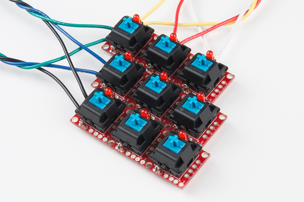 |
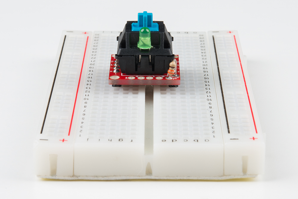
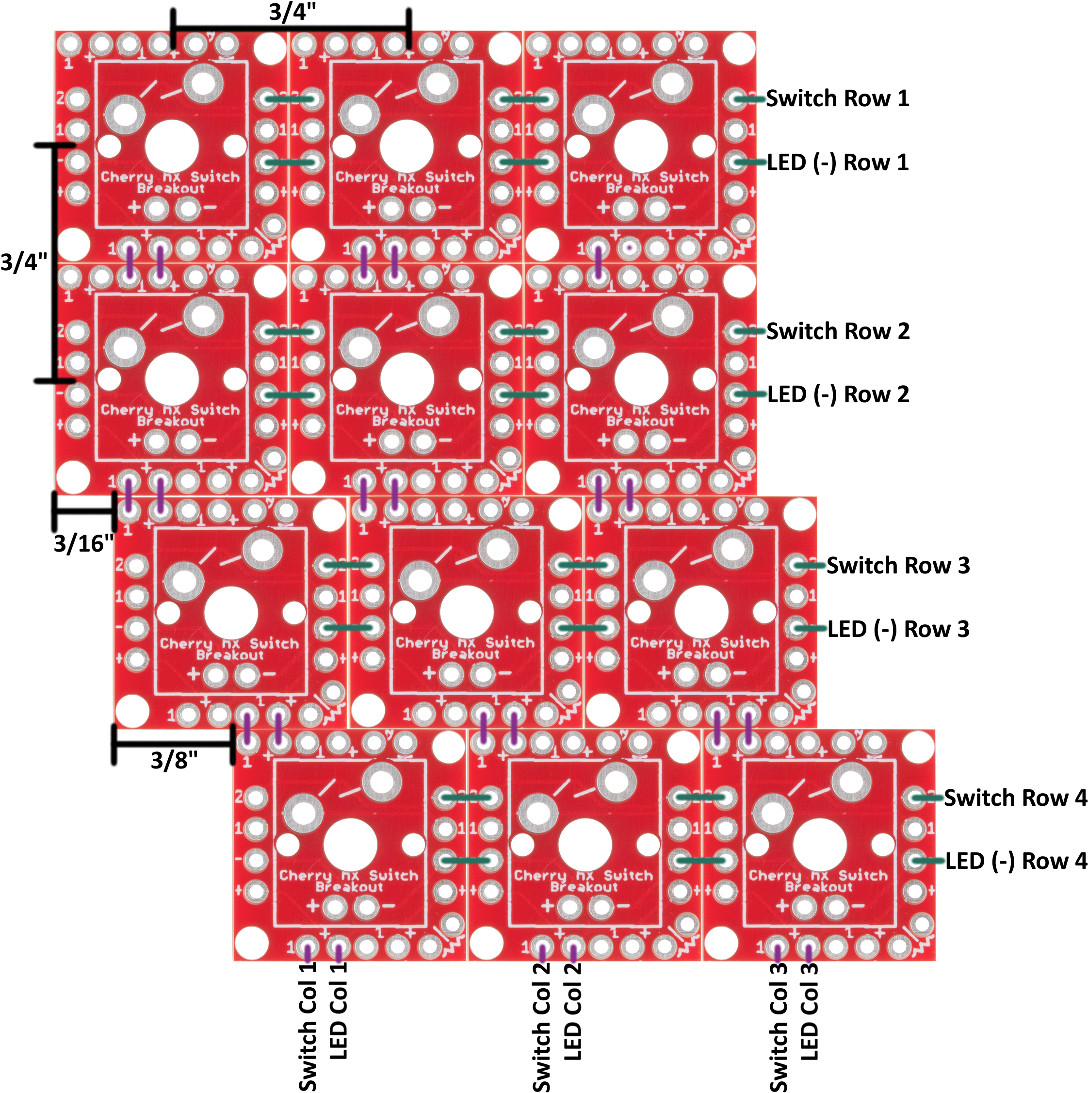
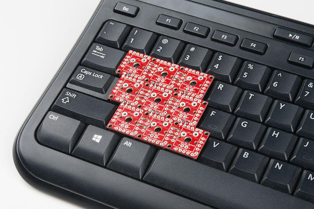
| Cherry MX Switch in action | Matrixed Configuration |
The Cherry MX Switch Breakout is a perfect prototyping tool for input devices ranging from a single key to fully-custom 101-key keyboards.
Covered In This Tutorial
This tutorial documents the SparkFun Cherry MX Switch Breakout, providing an overview of the breakout, plus some assembly and usage tips. It's broken down into a few sections, which you can navigate around using the buttons on the right.
Or use these links below to skip ahead:
- Hardware Overview -- A breakdown of the Cherry MX Switch Breakout Board features.
- Assembly Tips -- Tips for adding headers, wires, resistors, and diodes to the breakout board.
- Testing the Circuit -- A simple circuit to test the switch, LED, and any other components you may add on.
- Matrixing Breakouts -- A guide to combining two or more breakout boards into a row/column matrix, and scanning them with an Arduino.
Bill of Materials
In addition to the Cherry MX Switch there are a few additional items you may want to add on to the Breakout Board.
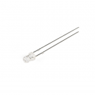
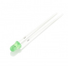
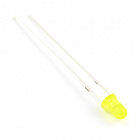
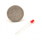
3mm LEDs can be placed inside the switch. Pick any color you please: red, green, yellow, or cycling.
The breakout board also provides a footprint for an optional LED-current-limiting resistor. 1/6W PTH resistors, like these 330Ω's, are recommended.
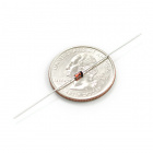
If you're matrixing multiple breakout boards together, you may want to add a small-signal diode to the board to help isolate the switches and prevent any possible "ghosting". Standard 1N4148 diodes should do the trick for this.
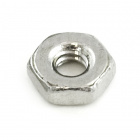
If you need to tie the board down, it has mounting holes designed to fit 2-56 screws and nuts.
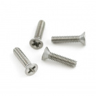
Screw - Flat Head (3/8", 2-56)
PRT-08992
Resistor 330 Ohm 1/6 Watt PTH - 20 pack
COM-11507You'll need soldering tools, including a soldering iron and solder. Other tools, like wire strippers, flush cutters, and a third hand, can also be helpful.


Flush Cutters - Xcelite
TOL-14782Finally, headers or wire will help connect the breakout board to your breadboard or development platform.
Suggested Reading
This hookup guide relies on some beginner-level electronics knowledge. If any of the subjects below sound foreign to you, consider checking out that tutorial first:
Resistors
Diodes
Button and Switch Basics
Light-Emitting Diodes (LEDs)
Hardware Overview
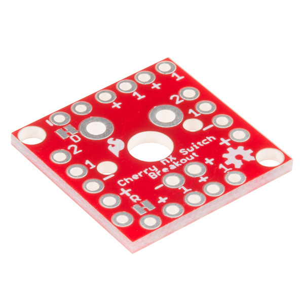
While it may seem like a simple breakout, the Cherry MX Switch Breakout board is a little over-engineered. Here's a quick breakdown of the pin breakouts and additional features of the board.
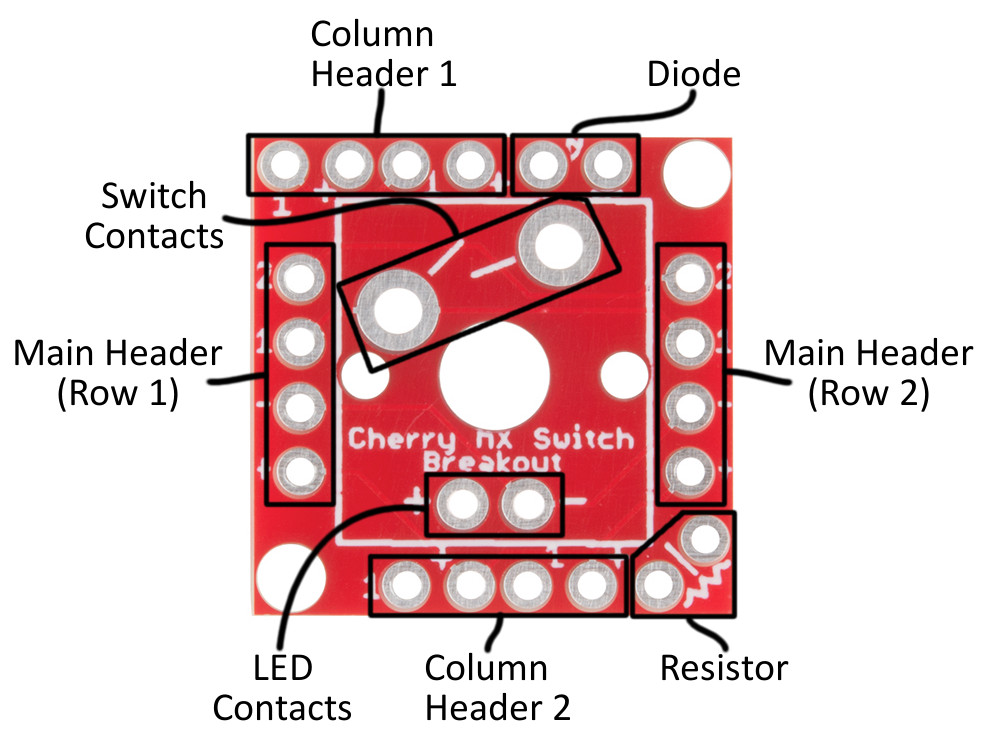
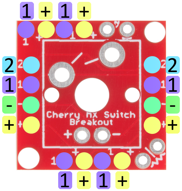
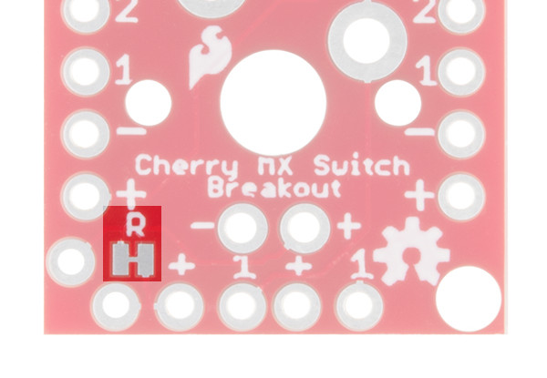
Breakout Pin Labels
Up to four pins are used to interact with the Cherry MX Switch -- two for the switch contacts and two for the optional LED. These pins are broken out on all sides of the board, labeled either "1", "2", "+", or "-". Those labels are short for:
| Pin Label | Pin Description |
|---|---|
| 1 | Switch contact 1 |
| 2 | Switch contact 2 |
| + | LED anode |
| - | LED cathode |
If you only want to use the switch, the pins labeled "1" and "2" should be all you need. If you're integrating a 3mm LED, the LED's anode and cathode will be accessible on the "+" and "-" pins respectively.
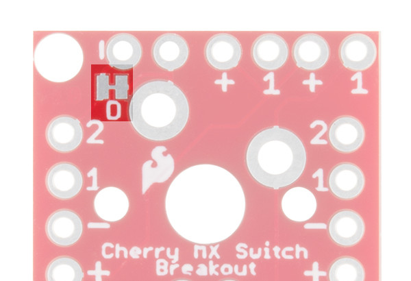
Header Pairs
Every side of the breakout board is equipped with a four-pin header (don't confuse them with the diode or resistor pins), but not all of these headers are created equally! Two headers break out all four pins, while the other two headers only break out the LED anode and one of the switch contacts.
The pair of headers on the left and right sides of the board break out all four pins. These are intended for primary use. You can solder male pins into both of these headers, and plug the switch into a breadboard.
The pair of headers breaking only the LED anode and switch contact 1 are designed for keypad matrices, where multiple boards are connected in row/column pairs. More on this later in the tutorial.
Assembly Tips
To use the breakout board, at a bare minimum you'll need to solder the Cherry MX Switch and either headers or wires to the "1" and "2" pins. Male headers work well for most breadboarding applications, while solid-core or stranded wire work well if you're wiring the breakout up to something afar.


There are plenty of other addon options, including a 3mm LED, current-limiting resistor, and switch isolating diodes, which are all documented below.
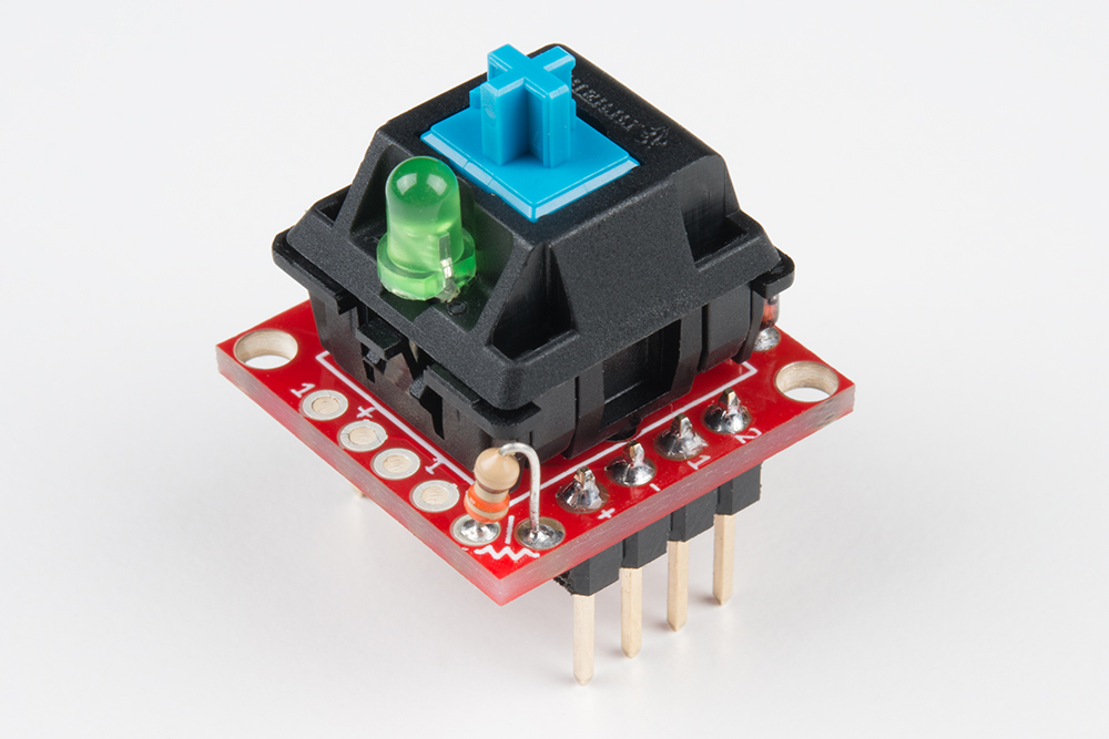
3mm LED
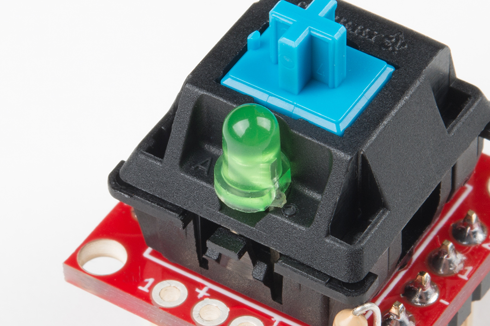
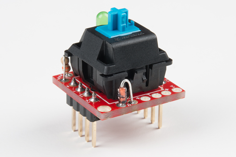
Most Cherry MX Switches -- including the blue, MX1A-E1NW switch we carry -- have a recess in their body designed to fit a small 3mm LED.
An "A" on the top side of the switch and a diode symbol on the backside both show the recommended polarity of the LED.

To add an LED to the switch, insert the anode and cathode legs of the LED into their respective pins -- the LED's longer, anode leg should be inserted into the "A" pin -- then flip the board over, and solder the LED to the breakout board.
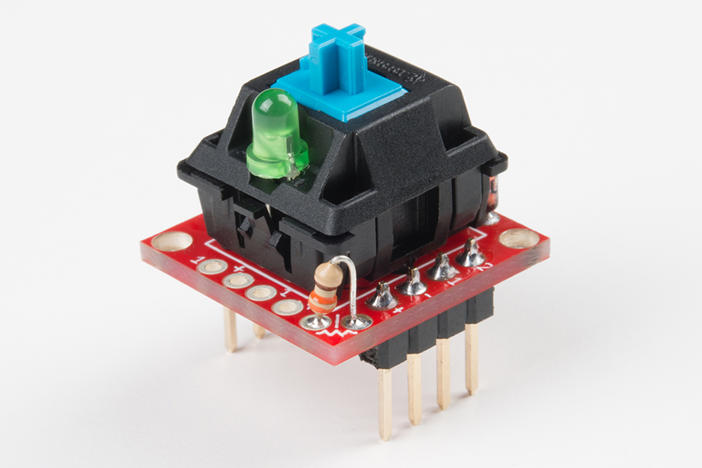
Adding a Current-Limiting Resistor
If you're adding an LED to the switch, more likely than not, you'll need a current-limiting resistor. The breakout provides a resistor footprint, in-line with the LED. You'll find the resistor pads on the bottom-right corner of the board.
To connect an LED to the board, bend one of the resistor legs so it's parallel with the other. Then insert both legs into the board like so:
You'll also need to cut the "R" jumper on the back side of the board, which might be easier to do before you solder anything. A hobby knife and a steady hand should do the trick.
By default, the board has a short across the current-limiting resistor. Cutting this jumper removes the short, and functionally adds the resistor to the circuit.
Ghost-Prevention Diode
If you plan on interconnecting four-or-more breakouts -- creating a row/column matrix of switches -- you may also want to consider adding a small-signal diode to help prevent "ghosting". The 1N4148 small-signal diode is perfectly fit for this task.
Switch Matrix Ghosting
"Ghosting" is a problem that can adversely affect the detection of multiple, simultaneous button presses. Without diode protection, certain combinations of simultaneous button-presses can cause one-or-more un-actuated buttons to appear pressed ("ghosted"). The result is a false-positive key-press, which can cause undesired behavior in a project.
To avoid button ghosting, small-signal diodes can be placed in-circuit, after every key. The diode prevents a key's signal from "backfeeding" back through the line.
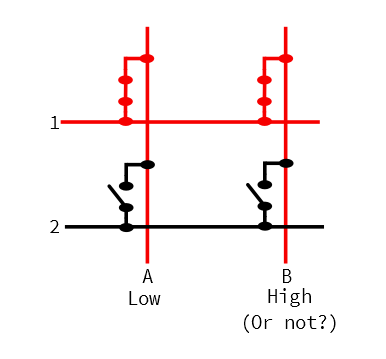
While the diode does prevent ghosting, it does place certain restrictions on your button-press detection. It forces the switch contact on the diode's anode (positive) side to be at a higher voltage than the other contact, as the switch can only conduct meaningful current in one direction.
For more on keypad ghosting, check out Byron's explanation in the Button Pad Hookup Guide.
A small, "vertical" diode footprint is broken out in the upper-right corner of the board. Near one of the pads in this footprint, a small, white line designates which pin should be connected to the diode's cathode (negative) pin.
To solder a diode into the board, bend the anode leg down, so it's parallel with the cathode leg. Then insert the diode into the board -- making sure to place the cathode leg (usually indicated by a black bar) into the marked hole.
You'll also need to cut the "D" jumper on the back side of the board -- otherwise the diode will be shorted over. (This may be easier if you do it before soldering anything.)
Like the resistor, the breakout shorts across the diode. Cutting this jumper removes the short and functionally adds the diode to the circuit.
Mounting Hole Size
A pair of mounting holes are provided on opposite corners of the breakout board. These holes are designed to fit 2-56 (3/8") screws. Flat heads are recommended, though rounded heads can work as well.
Screw - Flat Head (3/8", 2-56)
PRT-08992If you're going to be doing a lot of jamming on your keyboard, you'll want it tied down!
Testing the Circuit
With just a power supply and a few wires, you can create a quick circuit to test out your switch, LED, resistor and diode. Wire up the "+" pin to 5V (or 3.3V). Then connect "-" and "1" together. And wire up "2" to ground. (If you didn't add a current-limiting resistor, make sure you add one externally! It can take the place of the wire from "+" to power, or 2 to ground.)
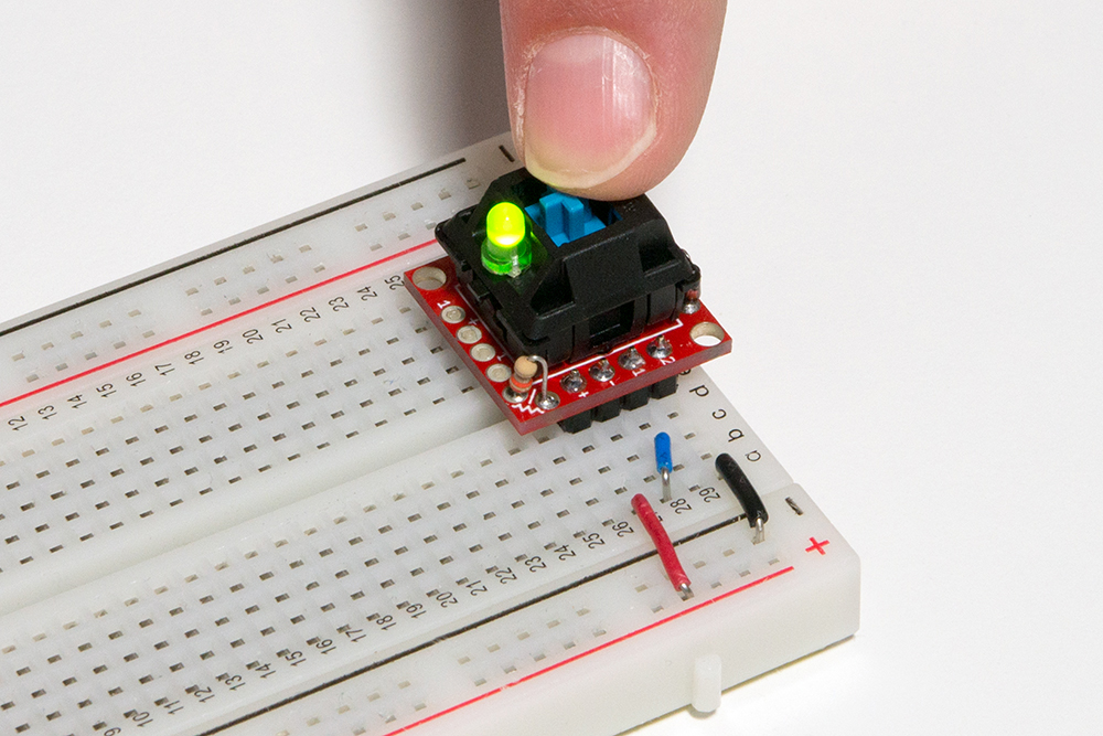
Now actuate the switch, and watch for the LED to illuminate.
Note that, if you've added the ghosting diode, this is the only polarity in which the switch will work -- pin 1 must be at a higher voltage than pin 2.
Matrixing Breakouts
The Cherry MX Switch Breakout Board's are designed with switch matrix-ing in mind. By creating a row/column matrix of switches, you can save on potentially dozens of microcontroller I/O pins. A 64-key keyboard, for example, can be scanned with just 16 I/O pins.
Key Spacing
While there is no specific standard for keyboard key spacing, most full-size keyboard keys are spaced by 3/4" (0.75in) from center-to-center. Rows may be offset by either 3/8" (0.375in) or 3/16" (0.1875in), or not at all.

The breakout is designed to make typical key spacing as easy as possible. By cleverly jumping one board to the next, you can add any of the standard offsets to nearby rows.
So, plan out your keyboard, and grab a soldering iron!
Creating a Key Matrix
To create a matrix of switches, arrange your boards as desired. Along the rows, line up the "2", "1", "-", and "+" labels. You will, however, only connect the "2" and "-" pins across rows. Solder your rows together first:
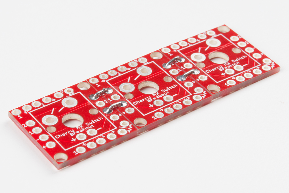
There’s not an easy method to soldering boards together. You’ll probably need wire strippers to split and cut solid-core wire into tiny (~3/8") pieces. A third hand can be a big-time help keeping boards stationary while you solder the little wires in place.
Once you've created your rows, line up the columns by matching the "1" and "+" pins. There are three offset options available, as documented in the image above.
Here is an example of a fully built-up 3x3 matrix. The middle row is offset from the top by 3/16", and the bottom row is offset from the middle by 3/8". This will make the middle row equivalent to a keyboard's A, S, and D keys, the top row Q, W, and E, and the bottom row Z, X, and C -- we're making a 9-key keypad centered around WASD!
Finish off the soldering job by connecting wires to the row and column pins you'll need access to. If you're not using any LEDs, you'll only need to solder to the "1" pins along the rows, and "2" pins along the columns.
Don't forget to add your switches, and LEDs, resistors, or diodes, should your project require them!
Keypad Scanning Arduino Code
Here's a simple Arduino sketch, designed to work with a 9-key, 3x3 matrix, but easily expandable for larger keypads.
The sketch assumes a circuit like this:
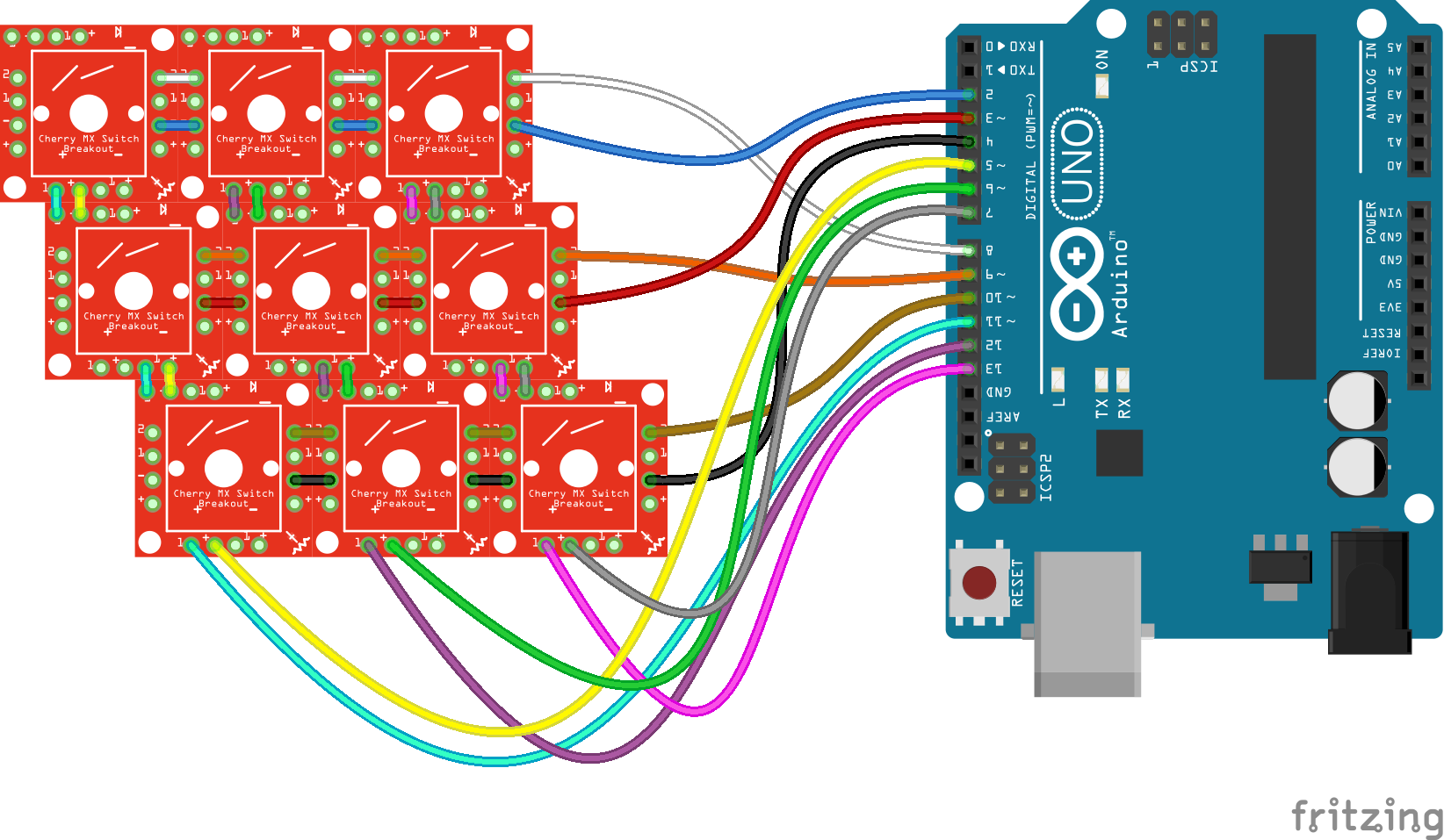
| Row/Column Name | Breakout Label | Arduino Pin |
|---|---|---|
| LED Row 1 | - | 2 |
| LED Row 2 | - | 3 |
| LED Row 3 | - | 4 |
| LED Column 1 | + | 5 |
| LED Column 2 | + | 6 |
| LED Column 3 | + | 7 |
| Switch Row 1 | 2 | 8 |
| Switch Row 2 | 2 | 9 |
| Switch Row 3 | 2 | 10 |
| Switch Column 1 | 1 | 11 |
| Switch Column 2 | 1 | 12 |
| Switch Column 3 | 1 | 13 |
Then copy this code and upload:
Note: This example assumes you are using the latest version of the Arduino IDE on your desktop. If this is your first time using Arduino, please review our tutorial on installing the Arduino IDE.
If you have not previously installed an Arduino library, please check out our installation guide.language:c
/* Button/LED Matrix Scanning Example - 3x3 Keypad
Code derived from Button Pad Hookup Guide Example 2
by Byron Jacquot @ SparkFun Electronics
https://learn.sparkfun.com/tutorials/button-pad-hookup-guide#exercise-2-monochrome-plus-buttons
*/
//////////////////////
// Config Variables //
//////////////////////
#define NUM_LED_COLS (3) // Number of LED columns (+, anode)
#define NUM_LED_ROWS (3) // Number of LED rows (-, cathode)
#define NUM_BTN_COLS (3) // Number of switch columns (isolating diode anode)
#define NUM_BTN_ROWS (3) // Number of switch rows (isolating diode cathode)
// Debounce built-in to the code. This sets the number of button
// high or low senses that trigger a press or release
#define MAX_DEBOUNCE (3)
////////////////////
// Hardware Setup //
////////////////////
static const uint8_t btnRowPins[NUM_BTN_ROWS] = {8, 9, 10}; // Pins connected to switch rows (2)
static const uint8_t btnColPins[NUM_BTN_COLS] = {11, 12, 13}; // Pins connected to switch columns (1)
static const uint8_t ledRowPins[NUM_LED_ROWS] = {2, 3, 4}; // Pins connected to LED rows (-)
static const uint8_t ledColPins[NUM_LED_COLS] = {5, 6, 7}; // Pins connected to LED cols (+)
//////////////////////
// Global Variables //
//////////////////////
static bool LED_buffer[NUM_LED_COLS][NUM_LED_ROWS]; // Keeps track of LED states
static int8_t debounce_count[NUM_BTN_COLS][NUM_BTN_ROWS]; // One debounce counter per switch
void setup()
{
Serial.begin(9600);
setupLEDPins();
setupSwitchPins();
// Initialize the debounce counter array
for (uint8_t i = 0; i < NUM_BTN_COLS; i++)
{
for (uint8_t j = 0; j < NUM_BTN_ROWS; j++)
{
debounce_count[i][j] = 0;
}
}
// Initialize the LED buffer
for (uint8_t i = 0; i < NUM_LED_COLS; i++)
{
for (uint8_t j = 0; j < NUM_LED_ROWS; j++)
{
LED_buffer[i][j] = 0; // All LED's off
}
}
}
void loop()
{
scan();
}
static void scan()
{
// Each run through the scan function operates on a single row
// of the matrix, kept track of using the currentRow variable.
static uint8_t currentRow = 0;
uint8_t i, j; // for loop counters
// Select current row, and write all components on that row LOW.
// That'll set the LED anode's LOW, and write the switch "2" pins LOW.
// If diodes were added, "2' should be connected to the diode cathode
digitalWrite(btnRowPins[currentRow], LOW);
digitalWrite(ledRowPins[currentRow], LOW);
// Look at the LED_buffer variable along this row.
// If any column is 1, turn the LED on.
// Otherwise LED will be left off
for (i = 0; i < NUM_LED_COLS; i++)
{
if (LED_buffer[currentRow][i])
{
digitalWrite(ledColPins[i], HIGH); // Turn LED on
}
}
// Scan through switches on this row:
for ( j = 0; j < NUM_BTN_COLS; j++)
{
// Read the button. If it's pressed, it should be LOW.
if (digitalRead(btnColPins[j]) == LOW)
{
if ( debounce_count[currentRow][j] < MAX_DEBOUNCE)
{ // Increment a debounce counter
debounce_count[currentRow][j]++;
if ( debounce_count[currentRow][j] == MAX_DEBOUNCE )
{ // If debounce counter hits MAX_DEBOUNCE (default: 3)
// Trigger key press -- Do anything here...
Serial.print("Key pressed ");
Serial.println((currentRow * NUM_BTN_COLS) + j);
LED_buffer[currentRow][j] = 1; // Set LED to turn on next time through
}
}
}
else // Otherwise, button is released
{
if ( debounce_count[currentRow][j] > 0)
{
debounce_count[currentRow][j]--; // Decrement debounce counter
if ( debounce_count[currentRow][j] == 0 )
{ // If debounce counter hits 0
// Trigger key release -- Do anything here...
Serial.print("Key released "); // Trigger key release
Serial.println((currentRow * NUM_BTN_COLS) + j);
LED_buffer[currentRow][j] = 0; // Set LED to turn off next time through
}
}
}
}
// Once done scanning, de-select the switch and LED rows
// by writing them HIGH.
digitalWrite(btnRowPins[currentRow], HIGH);
digitalWrite(ledRowPins[currentRow], HIGH);
// Then turn off any LEDs that might have turned on:
for (i = 0; i < NUM_LED_ROWS; i++)
{
digitalWrite(ledColPins[i], LOW);
}
// Increment currentRow, so next time we scan the next row
currentRow++;
if (currentRow >= NUM_LED_ROWS)
{
currentRow = 0;
}
}
static void setupLEDPins()
{
uint8_t i;
// LED drive rows - written LOW when active, HIGH otherwise
for (i = 0; i < NUM_LED_ROWS; i++)
{
pinMode(ledRowPins[i], OUTPUT);
digitalWrite(ledRowPins[i], HIGH);
}
// LED select columns - Write HIGH to turn an LED on.
for (i = 0; i < NUM_LED_COLS; i++)
{
pinMode(ledColPins[i], OUTPUT);
digitalWrite(ledColPins[i], LOW);
}
}
static void setupSwitchPins()
{
uint8_t i;
// Button drive rows - written LOW when active, HIGH otherwise
for (i = 0; i < NUM_BTN_ROWS; i++)
{
pinMode(btnRowPins[i], OUTPUT);
// with nothing selected by default
digitalWrite(btnRowPins[i], HIGH);
}
// Buttn select columns. Pulled high through resistor. Will be LOW when active
for (i = 0; i < NUM_BTN_COLS; i++)
{
pinMode(btnColPins[i], INPUT_PULLUP);
}
}
Whenever you press a switch, the LED on that switch should also light up. Releasing the switch turns the LED off.
Adapting the Code
The code is adaptable for larger or smaller matrices, with a few modifications towards the top of the sketch.
Modify the number of rows or columns in the Config Variables section:
language:c
//////////////////////
// Config Variables //
//////////////////////
#define NUM_LED_COLS (3) // Number of LED columns (+, anode)
#define NUM_LED_ROWS (3) // Number of LED rows (-, cathode)
#define NUM_BTN_COLS (3) // Number of switch columns (diode anode)
#define NUM_BTN_ROWS (3) // Number of switch rows (diode cathode)
And/or convert the pin connections in the Hardware Setup section:
language:c
////////////////////
// Hardware Setup //
////////////////////
static const uint8_t btnRowPins[NUM_BTN_ROWS] = {8, 9, 10}; // Pins connected to switch rows (2)
static const uint8_t btnColPins[NUM_BTN_COLS] = {11, 12, 13}; // Pins connected to switch columns (1)
static const uint8_t ledRowPins[NUM_LED_ROWS] = {2, 3, 4}; // Pins connected to LED rows (-)
static const uint8_t ledColPins[NUM_LED_COLS] = {5, 6, 7}; // Pins connected to LED cols (+)
If you've added ghost-prevention diodes, keep in mind that the switch's "1" pins (organized as the columns) must be at a higher potential than the row, "2" pins.
To scan the keypad matrix, we recommend pulling the row pins high using a pull-up resistor (often internal to I/O pins). Then progressively pulling the column pins to ground and checking which of the rows, if any, are pulled low as well.
Resources and Going Further
The Cherry MX Switch Breakout Board is open-source! If you want to check out the schematic or PCB design files, feel free to peruse our GitHub repository.
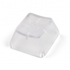
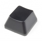
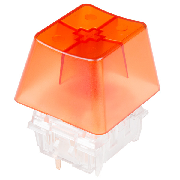
Keycaps and Alternative Sized Key
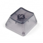
Once you've completed your keypad, consider topping off your keys with a keycap. There is a ridiculous variety to Cherry MX keycaps -- they vary by color, translucence, height, labels, and size. Below are a few options available in the catalog to top of your Cherry MX Switch.
If you are looking for more options, there are plenty of keycap sources out there, including WASD Keyboards and MechanicalKeyboards.com. Once you have chosen your keycap and placed it on the key, it should look similar to the image below.
Or consider adding a key that is four times its normal size to your project!
NovelKeys Big Switch - Tactile
COM-14583If you'd like to keep exploring SparkFun tutorials for project ideas, here are some guide's we'd recommend:
Reaction Timer
WAV Trigger Hookup Guide V11
SX1509 I/O Expander Breakout Hookup Guide
Button Pad Hookup Guide
Or check out this blog post for inspiration and 3D print your own keycap.