Capacitor Kit Identification Guide
Capacitor Identification
Capacitor Marking Review
Let's face it, a Farad is a lot of capacitance. Capacitor values are usually tiny -- often in the millionths or billionths of a Farad. To express those small values succinctly, we use the metric system. The following prefixes are the modern convention*.
| Capacitor Metric Prefixes | |||
| Prefix | SI Notation | Fraction | Symbol |
| Microfarad | 10-6 | One Millionth | µf |
| Nanofarad | 10-9 | One Billionth | nf |
| Picofarad | 10-12 | One Trillionth | pf |
Mu (µ), the symbol for micro, can be an issue for typesetting. It's hard to type, and not every font has the symbol. At SparkFun, we often use the letter 'u' as a substitute. Sometimes the letter 'm' is used instead, resuiting in micro-Farads being abbreviated as 'mF.' Technically, there's also a "milli-Farad," but in practice, milli-Farads are almost never seen, with thousands of micro-Farads being much more common.
Time and geography have an influence as well. In older North American designs, nano-Farads are uncommon, with BOMs and schematics instead using only µF and pF, padded with leading or trailing zeros.
The Ceramic Caps
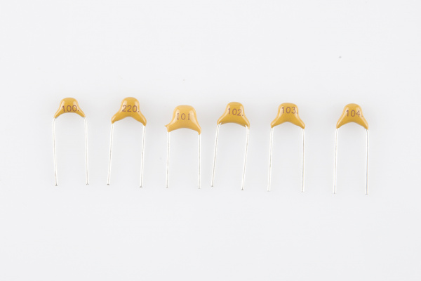
The smaller values in the kit are 50V rated ceramic capacitors. These are small, nonpolarized caps with yellow blob for their body.
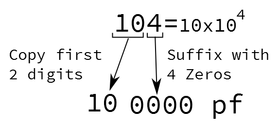
The value is printed on each in a three-digit code. This code is similar to the color code on resistors, but uses digits instead of colors. The first two digits are the two most significant digits of the value, and the third digit is the exponent on the 10. The value is expressed in terms of pico-Farads.
To decode the value, take the first two digits, then follow them with the number of zeros indicated by the third digit. 104 becomes "10" followed by "0000," or 100000 pF, more succinctly written as 100 nF.
Electrolytic Caps
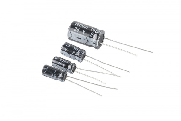
Electrolytic caps have larger, cylindrical bodies that look like small soda cans. They typically offer higher capacitance than ceramic caps. Unlike ceramics, they are polarized.
The markings on the 'lytic caps are easily legible -- the value and units are printed right on the body.
The value is followed with the voltage rating, indicating the maximum DC potential that the cap can withstand without damage. In this kit, the 1 µF is rated to 50V, the others are rated to 25V.
Polarized
The higher capacitance of electrolytics comes with a somewhat tedious detail -- they are polarized. The positive leg needs to be kept at a higher DC potential than the negative leg. If they're installed backwards, they're prone to explode.
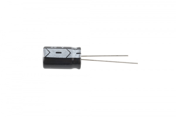
Thankfully, the leads are clearly marked.
There are two polarity indicators on an electrolytic cap:
- The stripe painted on the body usually denotes the negative lead.
- The positive lead is longer than the negative lead.


