This tutorial introduces matrix-scanning tecnniques, using the SparkFun 4x4 Button Pad to build an illuminated keypad.
More importantly, we'll introduce the concepts underlying the design and implementation of matrix scanning, so the reader can adapt and extend the techniques for their own projects.
This tutorial is structured as a series of progressive exercises. First, we'll explore the underlying concepts and underpinnings of the design. Then we'll apply what we've learned, assembling the PCB, and working through several applications, starting simply, then adding features and complexity.
Along the way, we'll explore some of the design decisions that contribute to the keypad, and look at some of the coding techniques that are used to control the hardware.
Even if you're just getting into the world of microcontrollers and embedded programming, you've probably hooked some buttons and LEDs up to your system, and written programs that let you turn the LEDs on and off using the buttons. It's fun to make an LED light up, and even more fun to have a switch that turns it on and off.
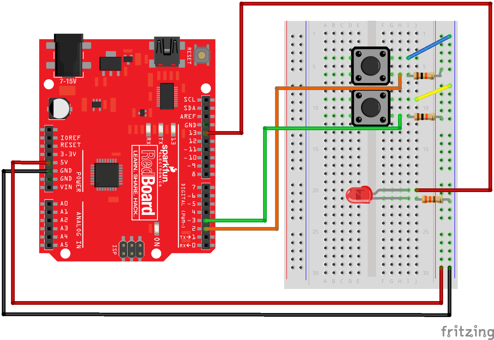
Exercises #3, #4, and #5 in the SIK Experiment Guide are versions of exactly that. In those experiments, a variety of LEDs and buttons are attached to a RedBoard, usually with one pin attached to a single button or LED.
If a couple switches and LEDs are fun, then heaps of LEDs and buttons are even better, right?
It naturally leads to questions about the limits of button and LED attachment. If a RedBoard allows 20 pins for digital I/O (digital pins 0-13, and repurposing A0 through A5 as digital), that allows a mix of buttons and LEDs totaling 20 units to be connected. This device-directly-to-pin connection strategy also assumes that we don't need to use pins for other purposes, such as serial communication.
That's a pretty serious constraint for many applications.
Let's look at a classic microcontroller system with a stylish "buttons & LEDs" user interface, the Roland TR-808 drum machine.
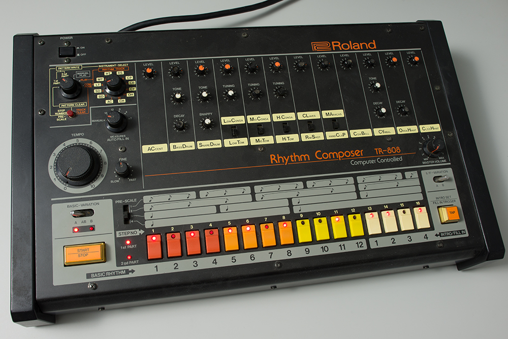
Across the lower edge of the control panel are 16 pushbutton switches, each with a captive red LED. The machine uses the LEDs to indicate its current status, and pressing a button causes the associated LED to toggle on and off.
The 808 was introduced in 1980. The NEC μPD650C microprocessor inside was state of the art for its day, running at 500 KHz (a screaming half megahertz!). It had nine 4-bit wide ports for I/O, but a number of those ports were consumed by the external memory bus (accessing the four KB of external RAM), leaving 20 pins for I/O.
But, the designers of the TR-808 connected all 32 of those components using only twelve I/O pins.
How did they do it? Let's look at that section of the schematic.
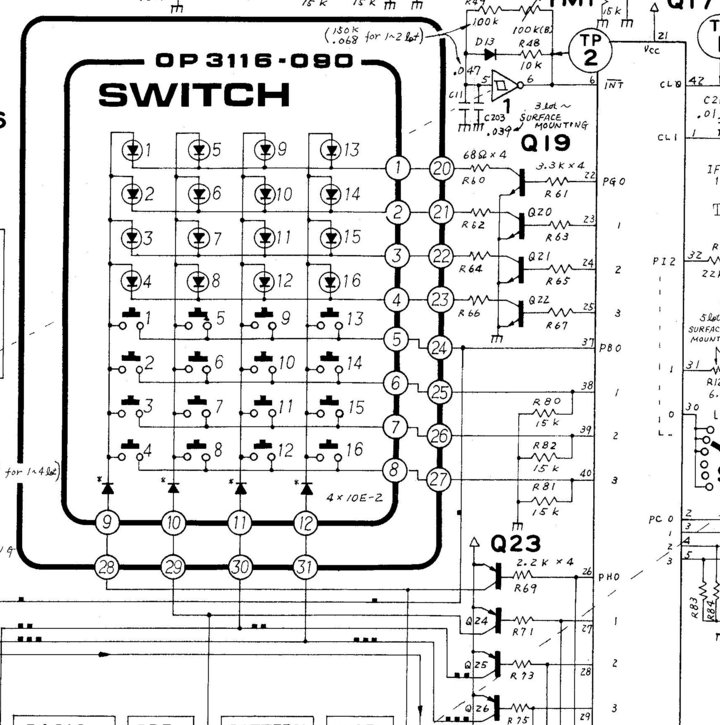
Here you see the LEDs near the top, the buttons below that, and the microcontroller along the left. The LEDs and buttons are in a scan matrix arrangement.
Matrix scanning is a common technique used to expand the number of inputs or outputs beyond the number of available pins. Matrix scanning requires some cleverness on both the hardware and software sides of the system -- there are some subtle factors at play.
To create a scan matrix, instead of using n pins directly as input or outputs, we allocate them as the axes of a Cartesian coordinate system -- think of them like lines of latitude and longitude. Matrices are usually described using the terms row for an X-axis group, and column for a Y-axis group. Any intersection in the matrix can be described using its X,Y or row, column coordinates.
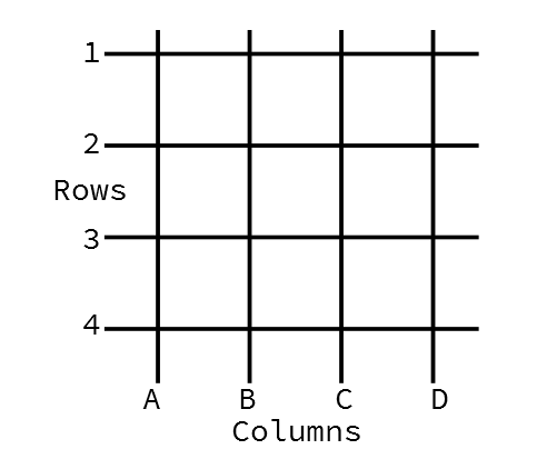
The scan matrix circuit places electronic components at the row, column intersections. By selecting a single row and column at a time, each component can be addressed uniquely.
Let's explore a simple example. Using four pins, we'll use two of them as row selectors, and the other two as column selectors. At each intersection in the matrix, we'll install a pushbutton switch that shorts the row to the column.
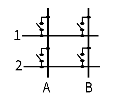
To use this matrix, we drive a single output at a time to select a column. While it's driven, we read the inputs. If we see the drive signal coming back on the input pins, we know that the switch at that X,Y position is closed.
Practical scan matrices often invert the voltages on the pins for a couple of clever reasons. Using inverted logic is called an active low system.
The scan consists of walking a logic low around the output pins, and looking for that low on the input pins.
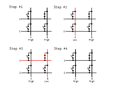
Above, the button at B1 is held. As the scan progresses, it does the following:
The process described above works well when a single button is held, but it can be problematic when more than one button is held at a time. Let's look at what happens when we press buttons A1 and B1 together.
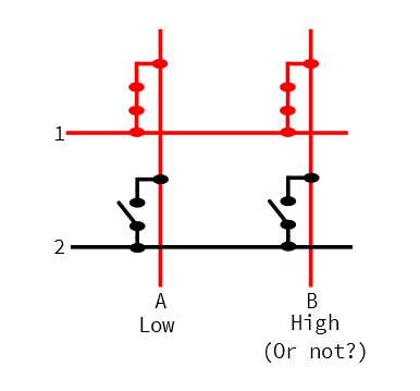
When the scanning sets column output A low, button A1 puts that low voltage onto row 1. Because B1 is also held, the low selection voltage from A is put onto column B, even though B is not selected, and putting a high level on the output pin.
This is a problem!
We have inadvertently connected two outputs together, and driven them to different logic levels. It's hard to predict what the voltage read by input 1 will be. Outputs A and B are contending, and the results depend on the specific architecture of the input and output pins.
Regardless of the actual result, connecting port pins together like this is considered poor practice. Ultimately, the circuit is too simple to be very useful.
To fix the above situation, diodes are put in series with each button, as shown below. The diodes isolate the scan columns from each other, even when multiple buttons are held simultaneously.
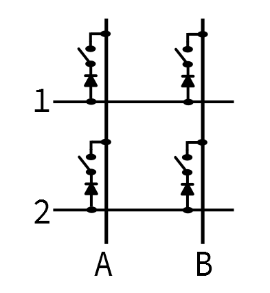
With the diodes in place, and we hold A1 and B1 at the same time, the diode on B1 won't conduct the row voltage back to column B. The short circuit no longer exists, and we can individually detect that A1 and B1 are pressed at the same time.
This circuit is commonly found in MIDI keyboards, where the microcontroller needs to be able to correctly detect that multiple keys are held simultaneously, in order to play chords.
This is also the sort of circuit used in high-quality PC keyboards. Being able to correctly detect arbitrary key combinations is known as N-Key Rollover. While it's not especially useful for everyday touch-typing, it can be very important for gaming, and alternate typing systems, such as braille, and chord typing.
We've seen how to scan a 2x2 key matrix for registering input. Now let's turn things around, and use a 2x2 LED matrix for output. The matrix places LEDs at the junctions of the matrix.
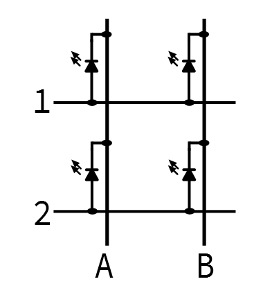
The LED matrix takes advantage of what we discussed in the switch matrix analysis, above -- diodes (or, more specifically, Light Emitting Diodes) only conduct in one direction, when the anode is at a higher voltage than the cathode. If both ends are at the same voltage (both high, or both low), or the diode is reverse biased (anode lower than cathode), then current doesn't flow, and the LED doesn't light up.
Differing from the button examples above, the driving pins are all configured as outputs. By carefully steering voltage onto the columns and rows, we control the voltage across the LEDs, allowing us to address each LED individually.
Let's look at how an active low scan would proceed if we want to light up B1, while leaving the other diodes dark.
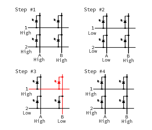
The LED is only illuminated while column B is being scanned. This takes advantage of how our eyes perceive the world around us -- when an LED flashes on and off quickly enough, we see it as being solidly illuminated (although it may appear to be less bright than a continuously lit LED.). This is one example of the phenomenon of persistence of vision.
To address more buttons or LEDs, we simply add columns and rows. For instance, if we wanted 16 buttons , we could add two rows and two columns, making a 4x4 matrix.
A 4x4 matrix almost brings us full circle, back to the Roland TR-808, with its 16 buttons and 16 LEDs. By including both buttons and LEDs, the 808 hits one last design optimization: the scan outputs for the switches are shared with the LEDs.
If we look a little more closely at the schematic, we see (from top to bottom)
The output pins in ports G and H are buffered using discrete transistors, since the port pins of the μPD650C aren't capable of sourcing or sinking the current required to get the LEDs to light up.
Port B has discrete pull-down resistors, an indication that this is an active-high scan matrix. The μPD650C doesn't have internal pull-ups, so there's no reason to invert the scan just to take advantage of them.
You'll also notice that instead of a diode per button, the column select lines each have a single diode -- this isolates the column selection outputs, but doesn't prevent misleading behavior if multiple switches are held simultaneously (although such presses can be detected and ignored in software).
We mentioned above that the scan matrix requires cleverness in both the hardware and software. Our discussion above has covered some of the clever hardware design issues, such as installing diodes to prevent contention, using active-low logic to take advantage of the internal pull-ups on port pins, and sharing select lines between the button and LED matrices.
There are a handful of other issues that a scanned matrix need to take into account, often handled by the associated software.
With the basic concepts of matrix scanning covered, lets look at how they're implemented in the 4x4 RGB Button Pad!
With the basics of matrix scanning established, let's look at how they work out in the SparkFun 4x4 RGB Button Pad.
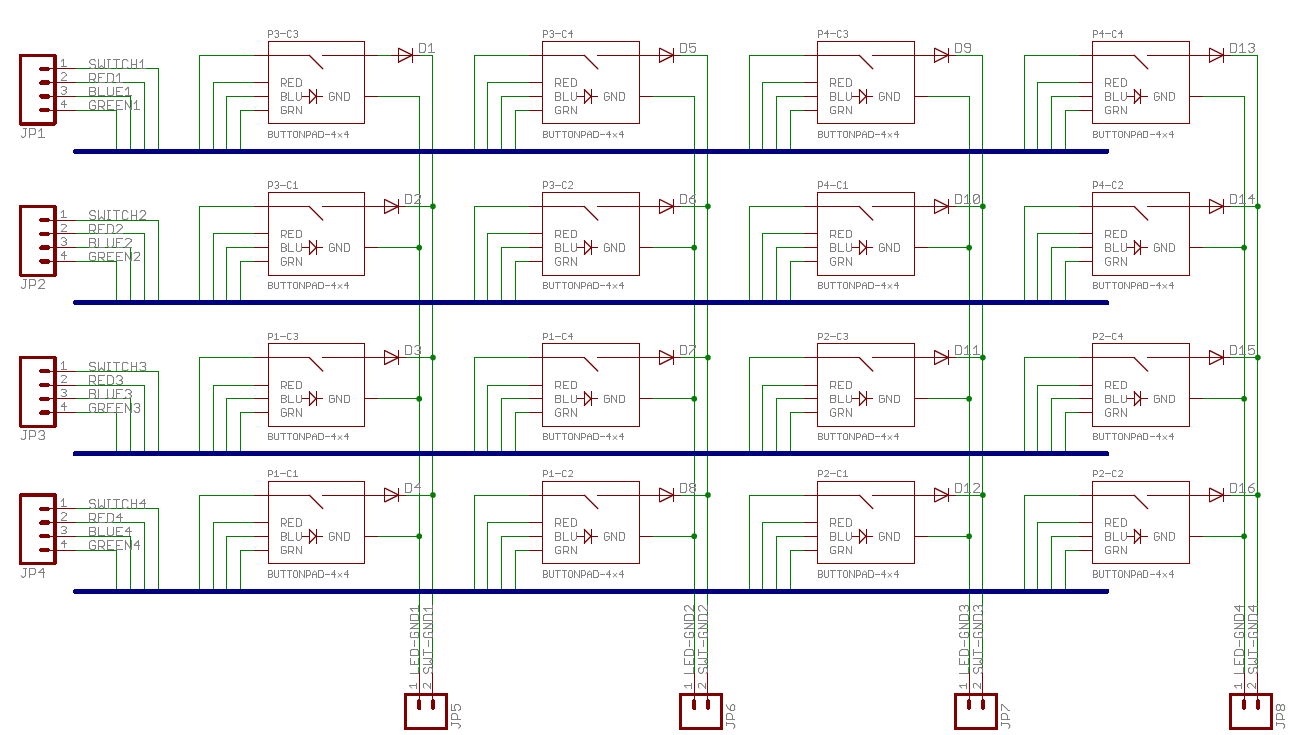
From what we explored in the previous section, we recognize the columns and rows. Each junction in the matrix consists of a pushbutton switch and RGB LED. The LEDs are a single envelope containing separate red, green and blue LEDs, which share a common cathode. The LEDs are set up as three overlapping 4x4 matrices, one for each color.
The Button pad PCB design dates from around 2008, relatively early in SFE history. As such, it's not completely up to our modern standards for labeling marking and labeling. Let's clarify a few points.
Let's assemble our keypad, and start working with it.
The following exercises use the items on the following wishlist.
You'll also need to following tools.
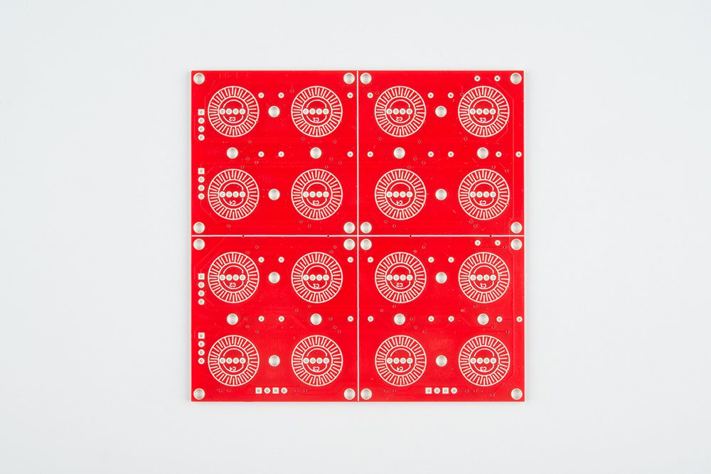
Before we assemble the button pad, let's take a closer look at some of the parts.
The PCB is designed with geometric features that interface with the button pad. The most obvious are the circular traces printed on top, with interlocking fingers that are bridged by the rings in the keypad, completing the button circuit.
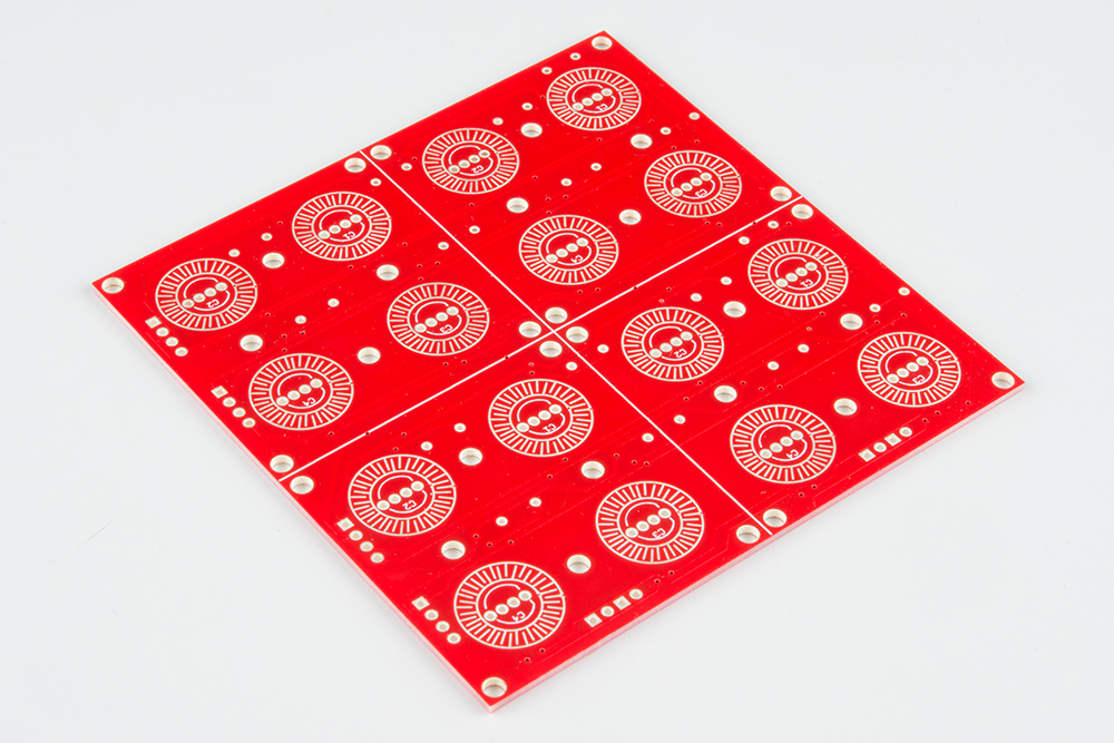
Inside each set of circles is the footprint for a common-cathode RGB LED.
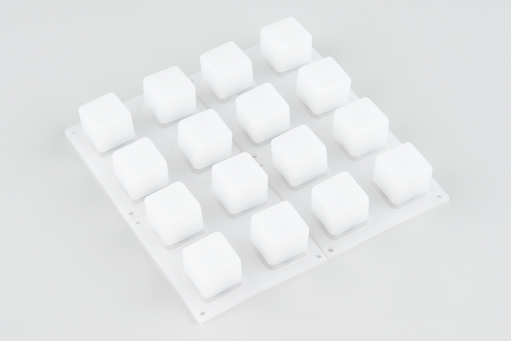
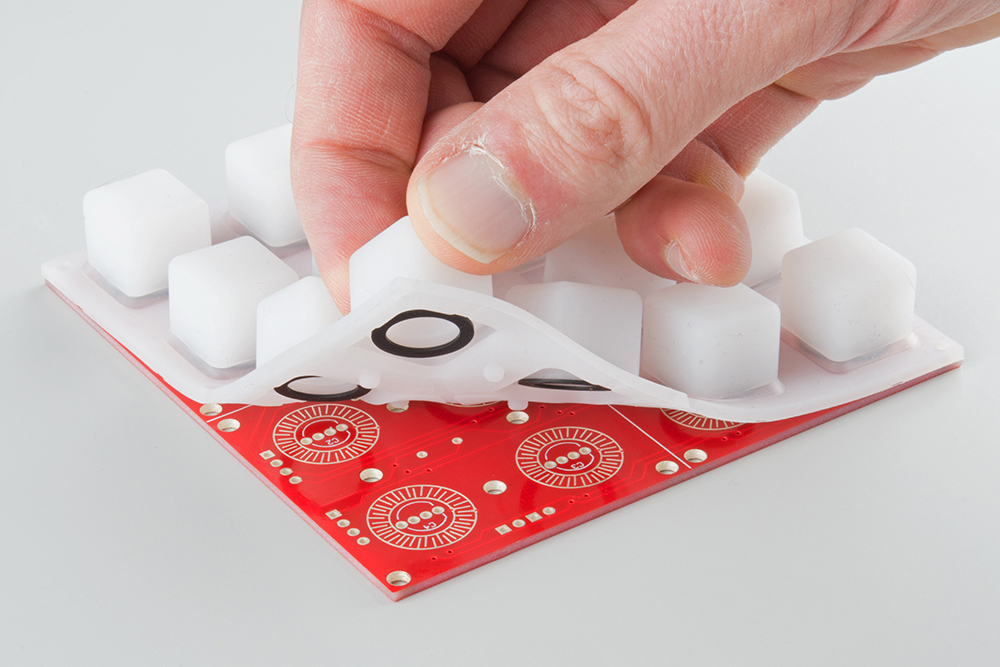
The 4x4 Rubber Keypad is molded from Dow Corning Silastictm Silicone rubber. It's similar to the keypads used by television remote controls.
If we flip it over, we'll see a some particular details molded into the rubber.
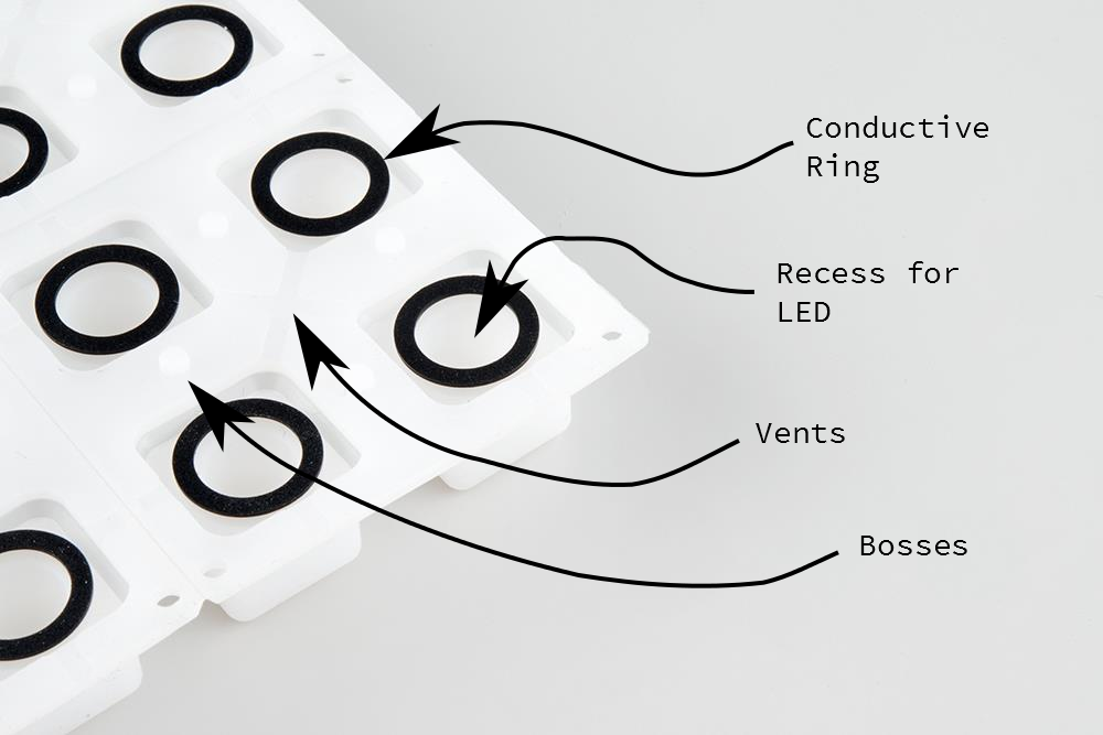
There are several features on the back of the button pad worth noting.
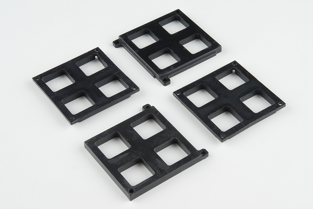
When the keypad is placed on the PCB, it is held in place by a set of brackets known as the "bezel."

There are actually four bezels in the wish list, two marked "bottom," and two marked "top." These designators indicate the positions the the bezels get installed in. The bottom bezels have tabs that stick out, and the top bezels have recesses those tabs fit into.
As we saw in the last section, the rubber button pad needs to sit on the PCB to work properly. If anything sticks up too far, the pad won't sit properly, and the buttons will be hard to press.
To keep the components appropriately short, we'll take a little extra care as we install them.
The 1n4148 diodes are installed on the back of the PCB, and would usually be soldered on the back of the board. However, since the resulting solder fillets would stick up too far, we'll actually trim them short, and then solder them from the back side of the PCB. It's a bit more work, but the end result is worth the effort.
There are 16 diodes. The diode locations on the PCB are simply marked with a rectangular outline, with a extra stripe at the cathode end.
To install the diodes, first, bend the leads of the diode to fit the holes in the PCB.
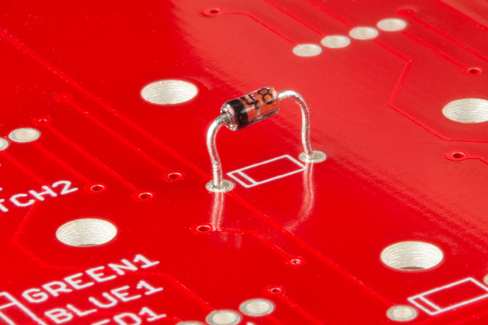
Push the diode down until the body touches the PCB, but don't solder it in. Instead, flip the board over and trim the leads flush.
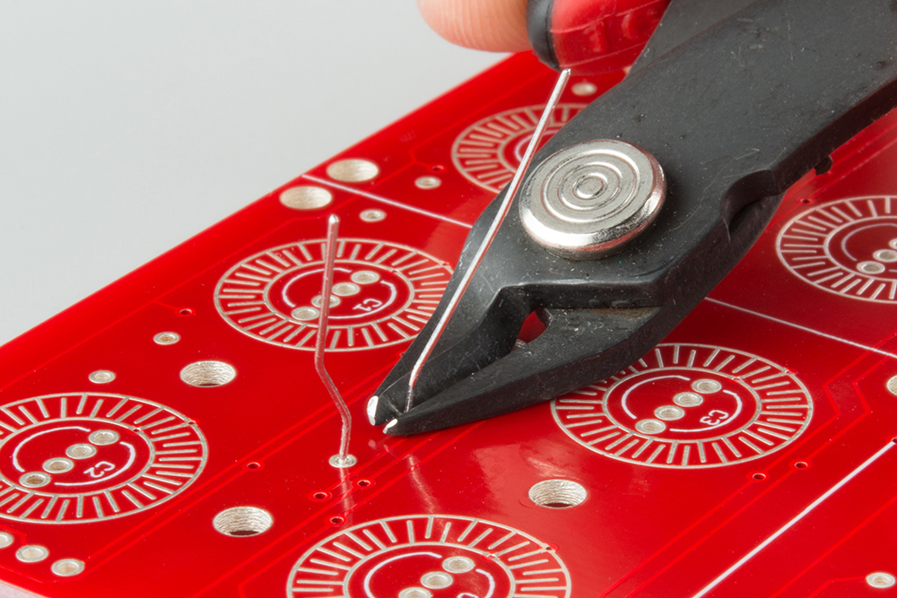
Then remove the trimmed diode, and snip a tiny bit more off the leads. We want to have enough lead left to fit into the hole on the PCB, but not so much that it protrudes.

Finally, put the diode back in the footprint, taking care to keep the cathode stripe pointed the correct direction, matching the silkscreen. Solder it in by tacking the remaining lead, adjacent to the diode body.
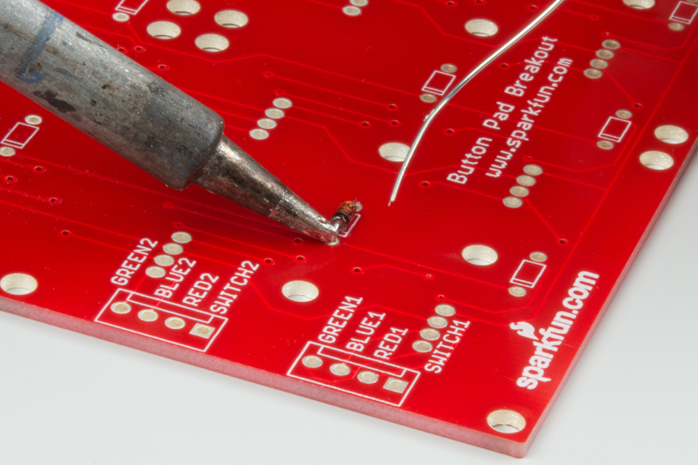
Before moving on, double-check that solder hasn't flowed through the hole, making a bump on the top of the PCB. If it has, you can cut it away with your flush cutters, or remove the bump with a bit of solder wick.
Each RGB LED has four leads. The anode of each color has its own pin, and they share a common cathode. The cathode is the longest pin of the bunch.
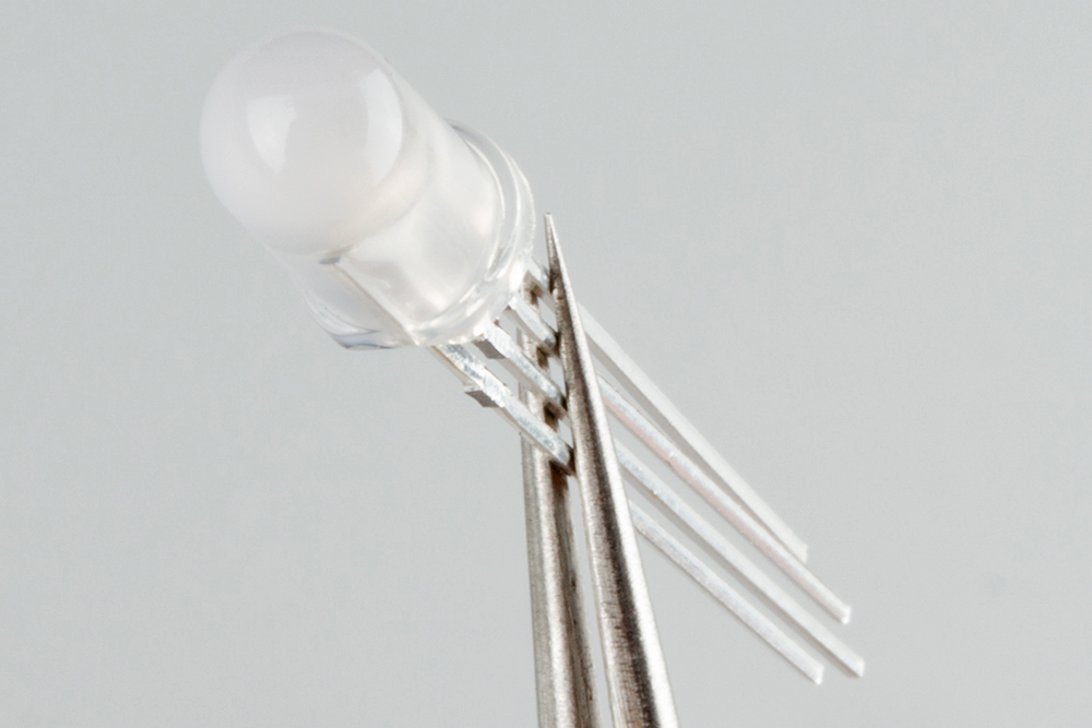
The LEDs are polarized. The body has a small flat edge at the base, that corresponds to the flat on the PCB silkscreen
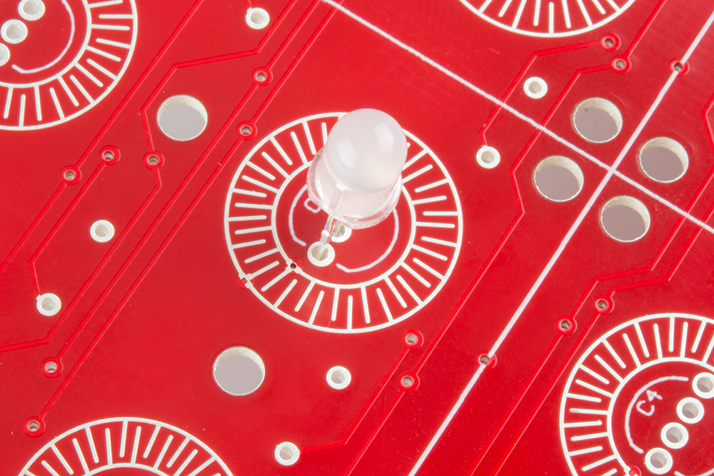
To put the LED on the PCB, insert the diode into the footprint. The longest lead is the second hole in from the flat, the other leads are each a bit shorter. With practice, you can insert the LED by "walking" it from side to side, and each lead will fall into place.
We need to cinch the LED up close to the PCB, to ensure that it will fit inside the recess in the button. If you're unsure about how tall it can be, you can test the fit with the keypad over the LED.
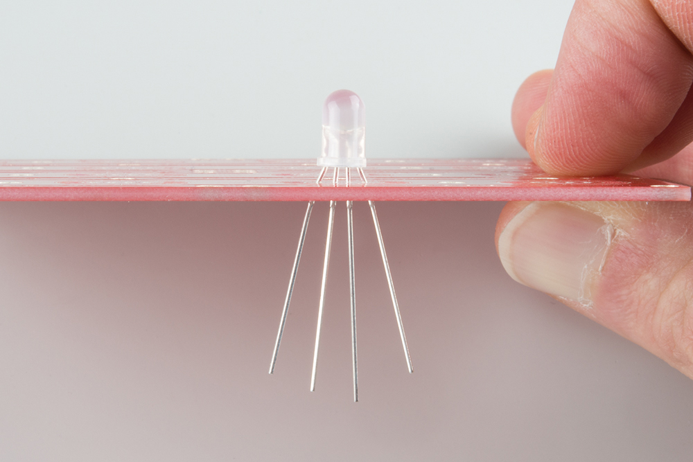
Before soldering, doublecheck the alignment of the flat side of the LED. When you're sure it's the right way around, solder it down, and snip the leads.
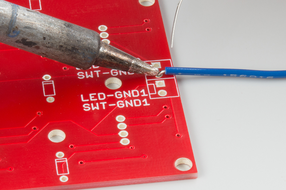
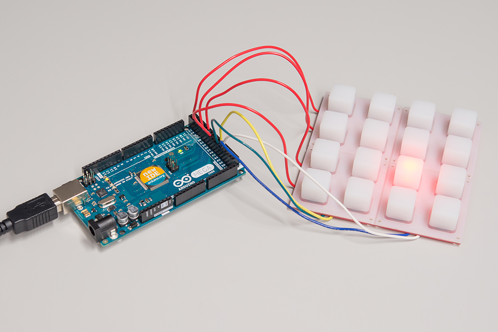
For the following exercises, we'll simply be using solid-core wire to connect the keypad to the Arduino Mega. If you've got a different application in mind, removable connectors or snappable headers might be more suitable. However you chose to connect the button pad, the goal should be to keep the connectors from protruding through the PCB, interfering with the rubber buttons
A fully populated 4x4 RGB button pad requires 24 wires to connect it to the microcontroller. We'll install the wires incrementally in the following sections, but each one will be installed using the same basic method. Like the 1N4148 diodes, we'll be soldering them from the back of the PCB, so they don't protrude and create bumps under the keypad.
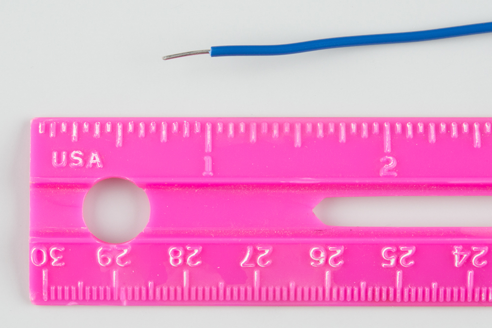
The exercises in this guide were done on a workbench, with the button pad sitting adjacent to the Mega. For that application, each wire was about 6" (15 cm) long.
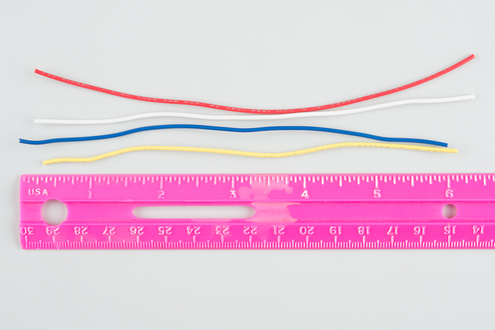
The PCB end of the wire was stripped to reveal about 0.1" of copper.
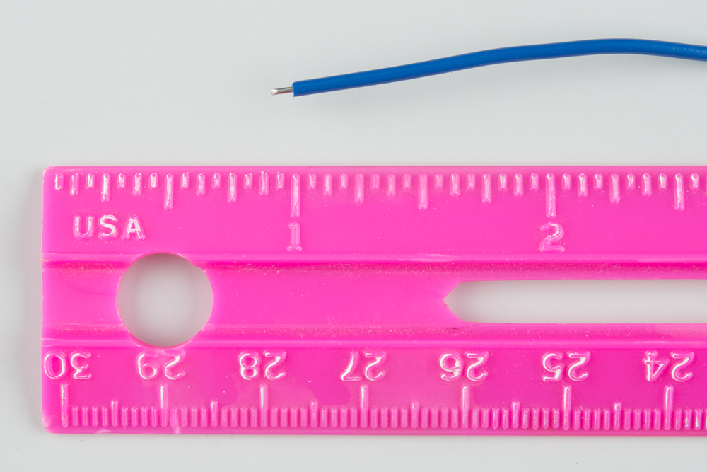
That end was bent into a gentle curve, and soldered to the PCB. Like the diodes, it was soldered from the back, and anything protruding on the button-side on the board was trimmed flush.
The other end was stripped about 0.25", so it could be inserted into the headers on the Mega.
The last assembly step is to place the buttonpad over the PCB...
...and secure it with the plastic bezels. Start with the "bottom" bezels (the ones with the protruding tabs), on opposite corners.
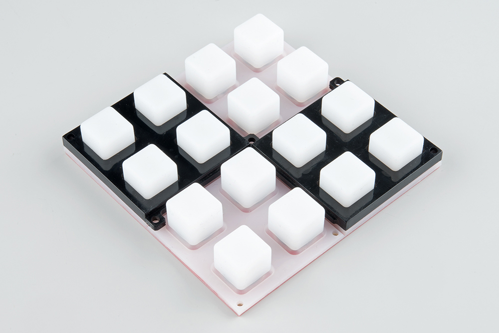
Then add the "top" bezels on the remaining corners.

Finally, insert the Philips screws, and thread them into the standoffs.

Take care to not overtighten the screws. We want to hold the button pad in place, but not tighten it so much that it gets damaged.
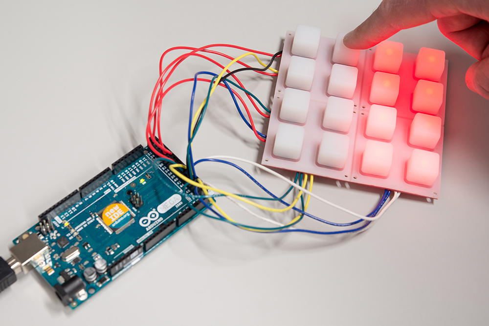
Our first exercise is to get the red LED scan working.
To start out, we need to wire up the parts of the matrix that hit the red LEDs -- the LED columns and the red LED row pins.
To make it easier to think about, set the button pad so that the button side is facing you, and connectors are on the left and bottom edges.
This keeps the rows and columns in a fairly sensible order and orientation. The columns are the connections across the bottom, and the rows are the connections up the left edge.
For 16 LEDs in a 4x4 matrix, that makes 4 rows + 4 columns = 8 connections total. These 8 connections are detailed in the following table.
| Function | Color | Button Pad Connection | Mega Connection |
| Red LED Row 1 | Red | Red1 | 22 |
| Red LED Row 2 | Red | Red2 | 30 |
| Red LED Row 3 | Red | Red3 | 33 |
| Red LED Row 4 | Red | Red4 | 36 |
| LED Column A | Green | LED-GND-4 | 42 |
| LED Column B | Yellow | LED-GND-3 | 43 |
| LED Column C | Blue | LED-GND-2 | 44 |
| LED Column D | White | LED-GND-1 | 45 |
You'll notice that the column selects are on adjacent pins, but the red LED rows are spaced apart -- this leaves the interceding pins for the corresponding green and blue connections.
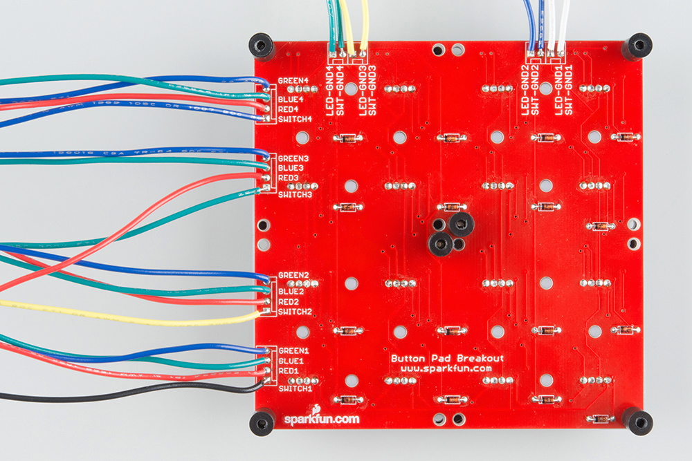
With the wires attached to the PCB, it will look like this:
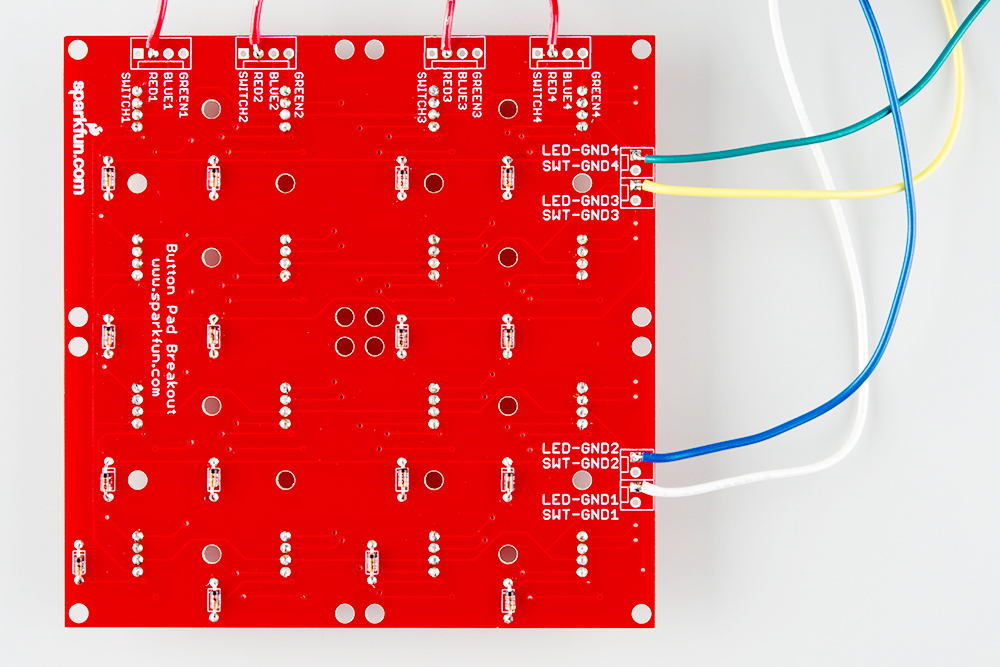
Each wire was prepared and soldered as described in the assembly section, and the end was stuck into the header on the Mega.
The following sketch illuminates a single red LED at a time. The illuminated LED walks around the matrix.
language:c

/******************************************************************************
red-only.ino
Byron Jacquot @ SparkFun Electronics
1/6/2015

Example to drive the red LEDs in the RGB button pad.

Exercise 1 in a series of 3.
https://learn.sparkfun.com/tutorials/button-pad-hookup-guide/exercise-1-monochrome-leds

Development environment specifics:
Developed in Arduino 1.6.5
For an Arduino Mega 2560

This code is released under the [MIT License](http://opensource.org/licenses/MIT).

Distributed as-is; no warranty is given.
******************************************************************************/
//config variables
#define NUM_LED_COLUMNS (4)
#define NUM_LED_ROWS (4)
#define NUM_COLORS (1)

// Global variables
static bool LED_buffer[NUM_LED_COLUMNS][NUM_LED_ROWS];
static int32_t next_advance;
static uint8_t led_index;

static const uint8_t ledcolumnpins[NUM_LED_COLUMNS]   = {42,43,44,45};
static const uint8_t colorpins[NUM_LED_ROWS] = {22,30,33,36};

static void setuppins()
{
  uint8_t i;

  // initialize all of the output pins

  // LED column lines
  for(i = 0; i < NUM_LED_COLUMNS; i++)
  {
    pinMode(ledcolumnpins[i], OUTPUT);

    // with nothing selected by default
    digitalWrite(ledcolumnpins[i], HIGH);
  }

  // LED row lines
  for(i = 0; i < NUM_LED_ROWS; i++)
  {
    pinMode(colorpins[i], OUTPUT);

    // with nothing driven by default
    digitalWrite(colorpins[i], LOW);
  }

}

static void scan()
{
  static uint8_t current = 0;
  uint8_t val;
  uint8_t i, j;

  // Select a column
  digitalWrite(ledcolumnpins[current], LOW);

  // write the row pins
  for(i = 0; i < NUM_LED_ROWS; i++)
  {
    if(LED_buffer[current][i])
    {
      digitalWrite(colorpins[i], HIGH);
    }
  }

  delay(1);

  digitalWrite(ledcolumnpins[current], HIGH);

  for(i = 0; i < NUM_LED_ROWS; i++)
  {
    digitalWrite(colorpins[i], LOW);
  }

  // Move on to the next column
  current++;
  if (current >= NUM_LED_COLUMNS)
  {
    current = 0;
  }

}

void setup()
{
  // put your setup code here, to run once:
  Serial.begin(115200);
  Serial.print("Starting Setup...");

  // setup hardware
  setuppins();

  // init global variables
  next_advance = millis() + 1000;
  led_index = 0;

  // Initialize the LED display array
  for(uint8_t i = 0; i < NUM_LED_COLUMNS; i++)
  {
    for(uint8_t j = 0; j < NUM_LED_ROWS; j++)
    {
      LED_buffer[i][j] = false;
    }
  }
  // Set the first LED in the buffer on
  LED_buffer[0][0] = true;

  Serial.println("Setup Complete.");

}

void loop()
{
  // put your main code here, to run repeatedly:

  scan();

  if(millis() >= next_advance)
  {
    next_advance = millis()+1000;

    LED_buffer[led_index/NUM_LED_COLUMNS][led_index%NUM_LED_COLUMNS] = false;
    led_index++;
    led_index %= (NUM_LED_COLUMNS * NUM_LED_ROWS);
    LED_buffer[led_index/NUM_LED_COLUMNS][led_index%NUM_LED_COLUMNS] = true;
  }
}
The code is an implementation if what we described in the background section. A column is selected, and the corresponding row pins are driven to get the LEDs to light.
Let's look at a few of the finer points in the code.
bool. The array dimensions match the rows and columns.scan() function.
delay(1), and you'll find that the LEDs get significantly dimmer.loop() calls the scan function every time it is invoked. Because it contains the delay(1) mentioned above, the scan updates at most once every millisecond.millis()), the loop walks the illuminated LED to the next position.The next exercise is to add button inputs to this, allowing you to turn each LED on or off by pressing the corresponding button.
Our Second exercise is to add the buttons to the scan matrix. We'll use them as inputs, to toggle the corresponding LEDs on and off.
We're going to assume that you're following this guide in order, and have just completed exercise #1. This exercise will describe the additions needed to add the button matrix, building incrementally on top of exercise #1.
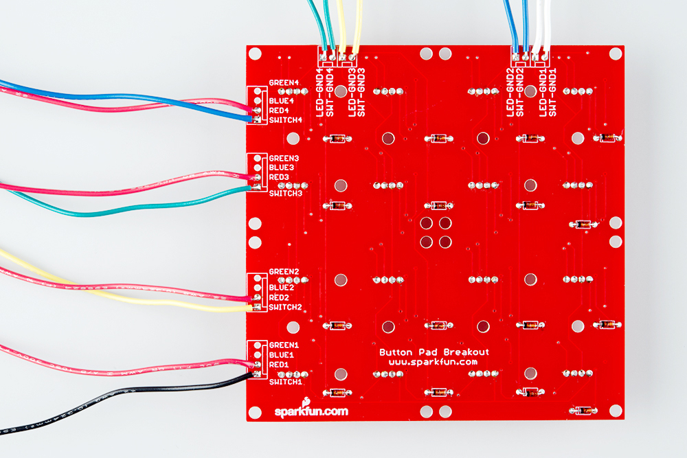
We're going to add another 8 wires to interface the button matrix. This breaks down as four button columns and four button rows, and described in the following table.
| Function | Wire Color | Button Pad Connection | Mega Connection |
| Button Row 1 | Black | Switch1 | 46 |
| Button Row 2 | Yellow | Switch2 | 47 |
| Button Row 3 | Green | Switch3 | 48 |
| Button Row 4 | Blue | Switch4 | 49 |
| Button Column A | Green | SWT-GND-4 | 50 |
| Button Column B | Yellow | SWT-GND-3 | 51 |
| Button Column C | Blue | SWT-GND-2 | 52 |
| Button Column D | White | SWT-GND-1 | 53 |
Again, the wires are prepared and soldered as described in the assembly section, and the other end is stuck into the header on the Mega. With these wires, we're adding column and row connections for the buttons. When they're in place, the connections to the PCB look like this.
The following sketch adds button support to the previous sketch.
language:c
/******************************************************************************
red-plus-buttons.ino
Byron Jacquot @ SparkFun Electronics
1/6/2015

Example to drive the red LEDs and scan the buttons of the RGB button pad.

Exercise 2 in a series of 3.
https://learn.sparkfun.com/tutorials/button-pad-hookup-guide/exercise-2-monochrome-plus-buttons

Development environment specifics:
Developed in Arduino 1.6.5
For an Arduino Mega 2560

This code is released under the [MIT License](http://opensource.org/licenses/MIT).

Distributed as-is; no warranty is given.
******************************************************************************/
//config variables
#define NUM_LED_COLUMNS (4)
#define NUM_LED_ROWS (4)
#define NUM_BTN_COLUMNS (4)
#define NUM_BTN_ROWS (4)
#define NUM_COLORS (1)

#define MAX_DEBOUNCE (3)

// Global variables
static bool LED_buffer[NUM_LED_COLUMNS][NUM_LED_ROWS];

static const uint8_t btncolumnpins[NUM_BTN_COLUMNS] = {50, 51, 52, 53};
static const uint8_t btnrowpins[NUM_BTN_ROWS]       = {46, 47, 48, 49};
static const uint8_t ledcolumnpins[NUM_LED_COLUMNS] = {42, 43, 44, 45};
static const uint8_t colorpins[NUM_LED_ROWS]        = {22, 30, 33, 36};

static int8_t debounce_count[NUM_BTN_COLUMNS][NUM_BTN_ROWS];

static void setuppins()
{
  uint8_t i;

  // initialize
  // select lines
  // LED columns
  for (i = 0; i < NUM_LED_COLUMNS; i++)
  {
    pinMode(ledcolumnpins[i], OUTPUT);

    // with nothing selected by default
    digitalWrite(ledcolumnpins[i], HIGH);
  }

  // button columns
  for (i = 0; i < NUM_BTN_COLUMNS; i++)
  {
    pinMode(btncolumnpins[i], OUTPUT);

    // with nothing selected by default
    digitalWrite(btncolumnpins[i], HIGH);
  }

  // button row input lines
  for (i = 0; i < NUM_BTN_ROWS; i++)
  {
    pinMode(btnrowpins[i], INPUT_PULLUP);
  }

  // LED drive lines
  for (i = 0; i < NUM_LED_ROWS; i++)
  {
    pinMode(colorpins[i], OUTPUT);
    digitalWrite(colorpins[i], LOW);
  }

  // Initialize the debounce counter array
  for (uint8_t i = 0; i < NUM_BTN_COLUMNS; i++)
  {
    for (uint8_t j = 0; j < NUM_BTN_ROWS; j++)
    {
      debounce_count[i][j] = 0;
    }
  }
}

static void scan()
{
  static uint8_t current = 0;
  uint8_t val;
  uint8_t i, j;

  // Select current columns
  digitalWrite(btncolumnpins[current], LOW);
  digitalWrite(ledcolumnpins[current], LOW);

  // output LED row values
  for (i = 0; i < NUM_LED_ROWS; i++)
  {
    if (LED_buffer[current][i])
    {
      digitalWrite(colorpins[i], HIGH);
    }
  }

  // pause a moment
  delay(1);

  // Read the button inputs
  for ( j = 0; j < NUM_BTN_ROWS; j++)
  {
    val = digitalRead(btnrowpins[j]);

    if (val == LOW)
    {
      // active low: val is low when btn is pressed
      if ( debounce_count[current][j] < MAX_DEBOUNCE)
      {
        debounce_count[current][j]++;
        if ( debounce_count[current][j] == MAX_DEBOUNCE )
        {
          Serial.print("Key Down ");
          Serial.println((current * NUM_BTN_ROWS) + j);

          // Do whatever you want to with the button press here:
          // toggle the current LED state
          LED_buffer[current][j] = !LED_buffer[current][j];
        }
      }
    }
    else
    {
      // otherwise, button is released
      if ( debounce_count[current][j] > 0)
      {
        debounce_count[current][j]--;
        if ( debounce_count[current][j] == 0 )
        {
          Serial.print("Key Up ");
          Serial.println((current * NUM_BTN_ROWS) + j);

          // If you want to do something when a key is released, do it here:

        }
      }
    }
  }// for j = 0 to 3;

  delay(1);

  digitalWrite(btncolumnpins[current], HIGH);
  digitalWrite(ledcolumnpins[current], HIGH);

  for (i = 0; i < NUM_LED_ROWS; i++)
  {
    digitalWrite(colorpins[i], LOW);
  }

  current++;
  if (current >= NUM_LED_COLUMNS)
  {
    current = 0;
  }

}

void setup()
{
  // put your setup code here, to run once:
  Serial.begin(115200);

  Serial.print("Starting Setup...");

  // setup hardware
  setuppins();

  // init global variables
  for (uint8_t i = 0; i < NUM_LED_COLUMNS; i++)
  {
    for (uint8_t j = 0; j < NUM_LED_ROWS; j++)
    {
      LED_buffer[i][j] = 0;
    }
  }

  Serial.println("Setup Complete.");

}

void loop() {
  // put your main code here, to run repeatedly:

  scan();

}
Once the code is loadeed, the keypad doesn't do anything on its own, but when you press a button, the corresponding LED toggles on and off.
The button scan is added in parallel to the LED scan. A column is selected, and a row is read. Some new definitions have been added to dimension the button matrix, plus some new data tables to define the pins for those functions.
The most complex part of this code is the button press detection, which involves a little extra work. When the buttons open or close, sometimes the change isn't especially clean -- the contacts might chatter or bounce when they close. The waveforms below show a couple of different switch actuations, captures from this button pad.
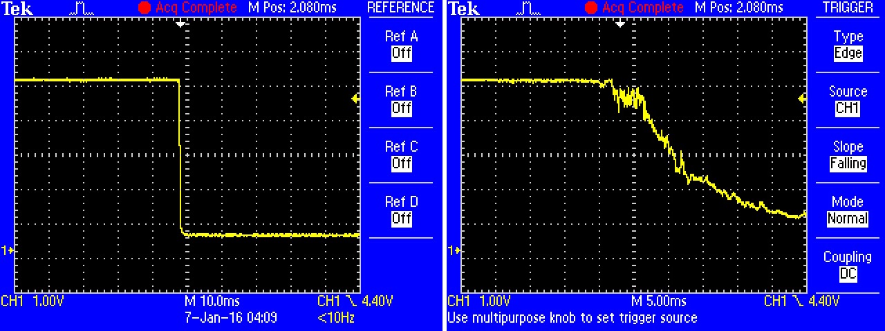
The nice closure on the left was the result of pressing the button quickly and decisively, straight down. The closure on the right is the result of pushing the button slowly, at an oblique angle. The ring inside twisted down onto the fingers of the PCB contacts. In this instance it takes roughly 20 milliseconds for the button to close solidly.
The glitchiness can cause the scanning system to misinterpret the chatter as multiple keypresses, when in fact the button was only actuated once.
To prevent this, the software uses some logic to perform debouncing. The scan system has to find a switch closed for several scans in a row before it decides that the switch is actually closed. It uses the two-dimensional array debounce_count to keep track of the number of successive scans. When a switch is found closed, the counter is incremented. When the counter reaches the constant MAX_DEBOUNCE, it decides that the switch has been solidly and cleanly closed, and acts on the keypress.
When a key is released, the counter counts back down to zero. This example prints a message when it detects a release. Some applications don't take any action on key releases (like the keypad on an ATM), but it's necessary in others (such as MIDI keyboards).
For the rubber button pad, a MAX_DEBOUNCE of 2 or 3 seems to work fairly well. Other types of buttons might require different debounce values.
With the red LEDs and buttons working, the final step is to get the green and blue LEDs working.
Hang in there, only 8 more wires to go!
With the red LEDs and buttons working, let's finish up by adding the blue and green LEDs to the mix.
| Function | Wire Color | Button Pad Connection | Mega Connection |
| Green Row 1 | Green | Blue1* | 24 |
| Blue Row 1 | Blue | Green1* | 26 |
| Green Row 2 | Green | Blue2* | 31 |
| Blue Row 2 | Blue | Green2* | 32 |
| Green Row 3 | Green | Blue3* | 34 |
| Blue Row 3 | Blue | Green3* | 35 |
| Green Row 4 | Green | Blue4* | 37 |
| Blue Row 4 | Blue | Green4* | 38 |
* Keep in mind that the LEDs we've used have their green and blue legs transposed when referencing the PCB markings. Yes, we are intentionally swapping green and blue in the wiring!
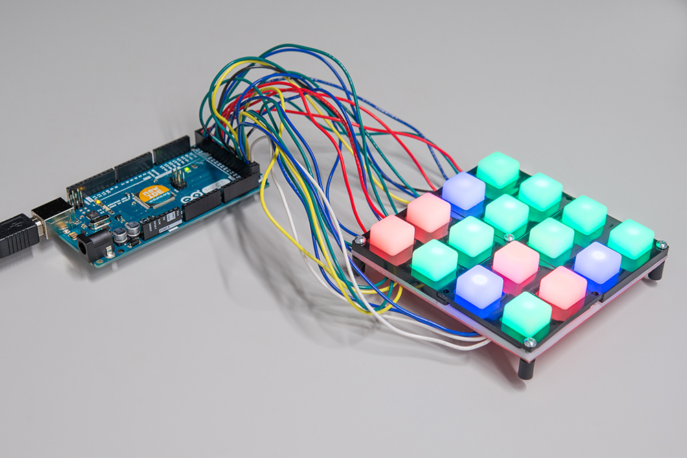
With all of these wires, it's starting to look like a bird's nest!
The final sketch builds on the previous two.
language:c

/******************************************************************************
rgb-plus-buttons.ino
Byron Jacquot @ SparkFun Electronics
1/6/2015

Example to drive the RGB LEDs and scan the buttons of the RGB button pad.

Exercise 3 in a series of 3.
https://learn.sparkfun.com/tutorials/button-pad-hookup-guide/exercise-3-rgb-leds-and-buttons

Development environment specifics:
Developed in Arduino 1.6.5
For an Arduino Mega 2560

This code is released under the [MIT License](http://opensource.org/licenses/MIT).

Distributed as-is; no warranty is given.
******************************************************************************/
//config variables
#define NUM_LED_COLUMNS (4)
#define NUM_LED_ROWS (4)
#define NUM_BTN_COLUMNS (4)
#define NUM_BTN_ROWS (4)
#define NUM_COLORS (3)

#define MAX_DEBOUNCE (3)

// Global variables
static uint8_t LED_outputs[NUM_LED_COLUMNS][NUM_LED_ROWS];
static int32_t next_scan;

static const uint8_t btnselpins[4]   = {50,51,52,53};
static const uint8_t btnreadpins[4] = {46,47,48,49};
static const uint8_t ledselpins[4]   = {42,43,44,45};

// RGB pins for each of 4 rows
static const uint8_t colorpins[4][3] = {{22,24,26}, {30,31,32},{33,34,35},{36,37,38}};


static int8_t debounce_count[NUM_BTN_COLUMNS][NUM_BTN_ROWS];

static void setuppins()
{
    uint8_t i;

    // initialize
    // select lines
    for(i = 0; i < NUM_LED_COLUMNS; i++)
    {
        pinMode(ledselpins[i], OUTPUT);

        // with nothing selected by default
        digitalWrite(ledselpins[i], HIGH);
    }

    for(i = 0; i < NUM_BTN_COLUMNS; i++)
    {
        pinMode(btnselpins[i], OUTPUT);

        // with nothing selected by default
        digitalWrite(btnselpins[i], HIGH);
    }

    // key return lines
    for(i = 0; i < 4; i++)
    {
        pinMode(btnreadpins[i], INPUT_PULLUP);
    }

    // LED drive lines
    for(i = 0; i < NUM_LED_ROWS; i++)
    {
        for(uint8_t j = 0; j < NUM_COLORS; j++)
        {
            pinMode(colorpins[i][j], OUTPUT);
            digitalWrite(colorpins[i][j], LOW);
        }
    }

    for(uint8_t i = 0; i < NUM_BTN_COLUMNS; i++)
    {
        for(uint8_t j = 0; j < NUM_BTN_ROWS; j++)
        {
            debounce_count[i][j] = 0;
        }
    }
}

static void scan()
{
  static uint8_t current = 0;
  uint8_t val;
  uint8_t i, j;

    //run
    digitalWrite(btnselpins[current], LOW);
    digitalWrite(ledselpins[current], LOW);

    for(i = 0; i < NUM_LED_ROWS; i++)
    {
        uint8_t val = (LED_outputs[current][i] & 0x03);

        if(val)
        {
            digitalWrite(colorpins[i][val-1], HIGH);
        }
  }


  delay(1);

  for( j = 0; j < NUM_BTN_ROWS; j++)
  {
    val = digitalRead(btnreadpins[j]);

    if(val == LOW)
    {
      // active low: val is low when btn is pressed
      if( debounce_count[current][j] < MAX_DEBOUNCE)
      {
        debounce_count[current][j]++;
        if( debounce_count[current][j] == MAX_DEBOUNCE )
        {
          Serial.print("Key Down ");
          Serial.println((current * NUM_BTN_ROWS) + j);

          LED_outputs[current][j]++;
        }
      }
    }
    else
    {
      // otherwise, button is released
      if( debounce_count[current][j] > 0)
      {
        debounce_count[current][j]--;
        if( debounce_count[current][j] == 0 )
        {
          Serial.print("Key Up ");
          Serial.println((current * NUM_BTN_ROWS) + j);
        }
      }
    }
  }// for j = 0 to 3;

  delay(1);

  digitalWrite(btnselpins[current], HIGH);
  digitalWrite(ledselpins[current], HIGH);

  for(i = 0; i < NUM_LED_ROWS; i++)
  {
    for(j = 0; j < NUM_COLORS; j++)
    {
      digitalWrite(colorpins[i][j], LOW);
    }
  }

  current++;
  if (current >= NUM_BTN_COLUMNS)
  {
    current = 0;
  }
}

void setup()
{
  // put your setup code here, to run once:
  Serial.begin(115200);

  Serial.print("Starting Setup...");

  // setup hardware
  setuppins();

  // init global variables
  next_scan = millis() + 1;

  for(uint8_t i = 0; i < NUM_LED_ROWS; i++)
  {
    for(uint8_t j = 0; j < NUM_LED_COLUMNS; j++)
    {
      LED_outputs[i][j] = 0;
    }
  }

  Serial.println("Setup Complete.");
}

void loop() {
  // put your main code here, to run repeatedly:

  if(millis() >= next_scan)
  {
    next_scan = millis()+1;
    scan();
  }
}
Now, instead of toggling the red LEDs between on and off, pressing a button cycles between the different colors. The cycle is off, then red, then green, then blue, then off again.
If you've been following the code changes between each exercise, you can probably anticipate what has been added.
LED_outputs array.Through this guide, we've intentionally kept things simple, to demonstrate the matrix scanning concepts. We've only scratched the surface of the permutations of matrix scanning.
There are a lot of other variations on these ideas to consider, but we're leaving them as exercises for the reader.
As we discussed in the previous section, we're only lighting the red, green or blue section of each LED individually, to keep current consumption low. When the author was developing exercise #4, the initial implementation allowed for the RGB LEDs to be on in any combination. The end result was that if too many LEDs were lit simultaneously, they got dim, and the processor heated up. Ultimately, the exercise was revised to only use single colors.
If we want to light more than one section at a time, we can mix them to create other colors, but to do that, we'll need to source and sink additional current. One solution is to add current limiting resistors in series with each LED Anode, and buffer the signal with high-current line drivers.
If you're really clever, you can use pulse-width modulation to vary the LED brightness, for an even wider range of colors.
The sketches in the exercises were written to be portable. They use the Arduino pin definitions, and digitalRead, and digitalWrite functions, which makes them easy to move to other systems. For instance, you could move this code to a Teensy 3.2 by adjusting the pin numbers in the row and column arrays. But this means handling those individual bits one at a time.
Most microcontrollers define the port pins as adjacent bits in byte or word wide registers. If you're working with those registers, you can arrange the matrix to gang the digital I/O using byte and word reads and writes. It's just not as easy to move to a different microcontroller!
As an even more optimized keypad scan can take advantage of external pin interruts. The scanning is idle until a key is pressed. The key triggers an interrupt, which performs a single scan to determine which key is pressed. When all keys are released, the system idles again.
We can combine multiple keypads into a larger matrix by joining the adjacent rows and columns.
There are peripheral chips that can do the button and LED scanning. The SX1509 I/O expander has a mode that allows it to scan an 8x8 key matrix, and interrupt the host when a key press is detected.
The 4x4 button pad has a little brother, the 2X2 button pad, that pairs with a matching PCB. If you're building a 2x2 button pad, you'll need a single top bezel to hold it together.
The circuit of the 2x2 button pad is actually set up like a single row of the 4x4 pad, and could be added to the same scan matrix.
learn.sparkfun.com | CC BY-SA 3.0 | SparkFun Electronics | Niwot, Colorado