Bus Pirate v3.6a Hookup Guide
Introduction
The Bus Pirate is an electronics prototyping dream. It's packed with many of the tools needed when getting a project up and running. The Bus Pirate can perform a variety of test equipment functions such as measuring voltage and frequency as well as generating PWM signals.
Most of the functionality of the Bus Pirate revolves around serial protocols. The Bus Pirate can communicate on 1-wire, 2-wire, 3-wire, UART, I2C, SPI, and HD44780 LCD protocols. It also has a bitbang mode for other or custom options.
This guide is intended to be a quick overview and cover a few things not explicitly covered in the Bus Pirate documentation provided by Dangerous Prototypes.
Suggested Reading
The following concepts will be mentioned in this guide. If you are unfamiliar with any of them, check out the corresponding tutorial.
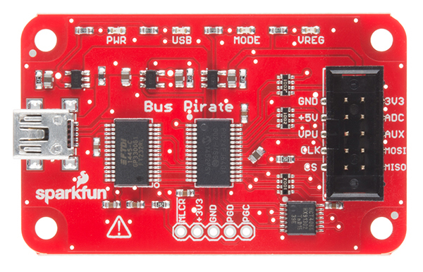
Board Overview
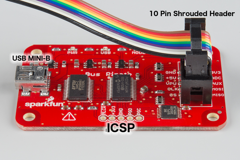
The Bus Pirate has 3 ports. This first is the ICSP port for directly programming the PIC microcontroller at the heart of this product. Since there is a bootloader and a reflashing utility, you shouldn't ever have to use this port.
The second port is a mini-B USB jack. Connect this to a computer with a standard A to mini-B cable. This provides the power to the board and allows you to communicate with Bus Pirate.
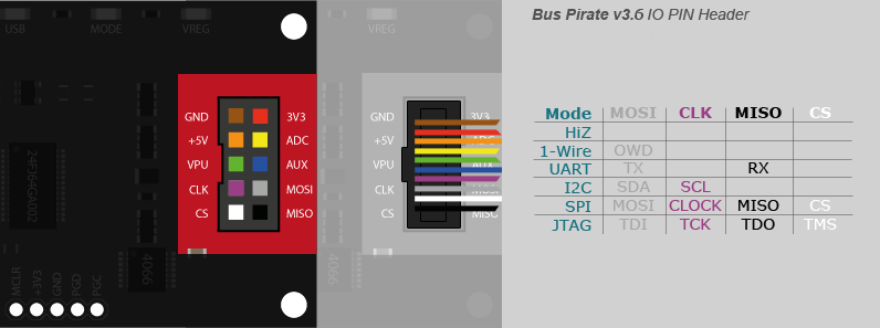
The third port is the most interesting. It's a shrouded 0.1" pitch 2x5 pin header. We sell a handy cable to connect the Bus Pirate to the system you are developing, debugging, or reverse engineering. Here is a graphic that shows maps the IO functions to the colors of the cable.
The following table describes in a little more detail the purpose of each pin. It's sorted in the same order as the conductors on the cable. The power supplies can be switched on or off in software, and each can supply up to 150mA to power your project.
| Pin Name | Description (Bus Pirate is the master) |
|---|---|
| GND | Ground, connect to ground of test circuit |
| +3.3V | +3.3 volt switchable power supply |
| +5.0V | +5 volt switchable power supply |
| ADC | Voltage measurement probe (max 6V) |
| VPU | Voltage input for on-board pull-up resistors (0V to 5V). |
| AUX | Auxiliary IO, frequency probe, pulse-width modulator |
| CLK | Clock signal (I2C, SPI, JTAG, KB) |
| MOSI | Master data out, slave in (SPI, JTAG), Serial data (1-Wire, I2C, KB), TX (UART) |
| CS | Chip select (SPI), TMS (JTAG) |
| MISO | Master data in, slave out (SPI, JTAG) RX (UART) |
Using the Bus Pirate
The Bus Pirate communicates with your host computer via a build in FTDI USB to UART bridge. For more information on using the standard FTDI drivers please refer to our tutorial on that.
The Bus Pirate has two interface modes, binary scripting mode, and user terminal mode.
Binary Scripting Mode
Binary scripting mode allows applications and/or scripts to control the Bus Pirate. This interface could be used to write a GUI, automated testing, etc. It's more work to get up and running, but it is more powerful. The following code block is a minimal Python script that can serve as a starting place to use the binary access mode on most platforms. It puts the Bus Pirate into binary mode, sends a command, and then prints out a response. It doesn't actually 'do anything' beyond that though; it's only a framework.
On my Mac I run a command like: ./binaryModeDemo.py -p /dev/tty.usbserial-AL00ESEJ. The default baud rate for the Bus Pirate is 115200. For help, run python binaryModeDemo.py --help. It should run on any platform running a Python interpreter. Some tweaks might be necessary if running a non-2.7 version of Python.
language:python
#!/usr/bin/env python
# encoding: utf-8
"""
Example code to interface the Bus Pirate in binary mode
Brent Wilkins 2015

This code requires pyserial:
    $ sudo pip install pyserial
or:
    $ sudo easy_install -U pyserial
"""
import sys
import serial
import argparse

commands = {
        'BBIO1': '\x00',    # Enter reset binary mode
        'SPI1':  '\x01',    # Enter binary SPI mode
        'I2C1':  '\x02',    # Enter binary I2C mode
        'ART1':  '\x03',    # Enter binary UART mode
        '1W01':  '\x04',    # Enter binary 1-Wire mode
        'RAW1':  '\x05',    # Enter binary raw-wire mode
        'RESET': '\x0F',    # Reset Bus Pirate
        'STEST': '\x10',    # Bus Pirate self-tests
}

def arg_auto_int(x):
    return int(x, 0)

class FatalError(RuntimeError):
    def __init__(self, message):
        RuntimeError.__init__(self, message)

def main():
    parser = argparse.ArgumentParser(description = 'Bus Pirate binary interface demo', prog = 'binaryModeDemo')

    parser.add_argument(
            '--port', '-p',
            help = 'Serial port device',
            default = '/dev/ttyUSB0')

    parser.add_argument(
            '--baud', '-b',
            help = 'Serial port baud rate',
            type = arg_auto_int,
            default = 115200)

    args = parser.parse_args()

    print '\nTrying port: ', args.port, ' at baudrate: ', args.baud

    try:
        port = serial.Serial(args.port, args.baud, timeout=0.1)
    except Exception as e:
        print 'I/O error({0}): {1}'.format(e.errno, e.strerror)
        print 'Port cannot be opened'
    else:
        print 'Ready!'
        print 'Entering binary mode...\n'

        count = 0
        done = False
        while count < 20 and not done:
            count += 1
            port.write(commands.get('BBIO1'))
            got = port.read(5)  # Read up to 5 bytes
            if got == 'BBIO1':
                done = True
        if not done:
            port.close()
            raise FatalError('Buspirate failed to enter binary mode')

        # Now that the Buspirate is in binary mode, choose a BP mode
        port.write(commands.get('RESET'))
        while True:
            got = port.readline()
            if not got:
                break
            print(got),

        """
        port.write(commands.get('SPI1'))
        got = port.read(4)
        if got == 'SPI1':
            print 'Entered binary SPI mode'
        else:
            raise FatalError('Buspirate failed to enter new mode')
        """

        port.close()


if __name__ == '__main__':
    try:
        main()
    except FatalError as e:
        print '\nA fatal error occurred: %s' % e
        sys.exit(2)
User Terminal Mode
Terminal mode is likely the interface of choice for most users, at least to start. It provides an interactive menu system for configuring the Bus Pirate. All one needs to use it is a terminal emulator.
The first thing to note is how to get help or list all of the commands. At the prompt enter ?.
Help:
HiZ>?
General                                 Protocol interaction
---------------------------------------------------------------------------
?       This help                       (0)     List current macros
=X/|X   Converts X/reverse X            (x)     Macro x
~       Selftest                        [       Start
#       Reset                           ]       Stop
$       Jump to bootloader              {       Start with read
&/%     Delay 1 us/ms                   }       Stop
a/A/@   AUXPIN (low/HI/READ)            "abc"   Send string
b       Set baudrate                    123
c/C     AUX assignment (aux/CS)         0x123
d/D     Measure ADC (once/CONT.)        0b110   Send value
f       Measure frequency               r       Read
g/S     Generate PWM/Servo              /       CLK hi
h       Commandhistory                  \       CLK lo
i       Versioninfo/statusinfo          ^       CLK tick
l/L     Bitorder (msb/LSB)              -       DAT hi
m       Change mode                     _       DAT lo
o       Set output type                 .       DAT read
p/P     Pullup resistors (off/ON)       !       Bit read
s       Script engine                   :       Repeat e.g. r:10
v       Show volts/states               .       Bits to read/write e.g. 0x55.2
w/W     PSU (off/ON)            <x>/<x= >/<0>   Usermacro x/assign x/list all
HiZ>
Example
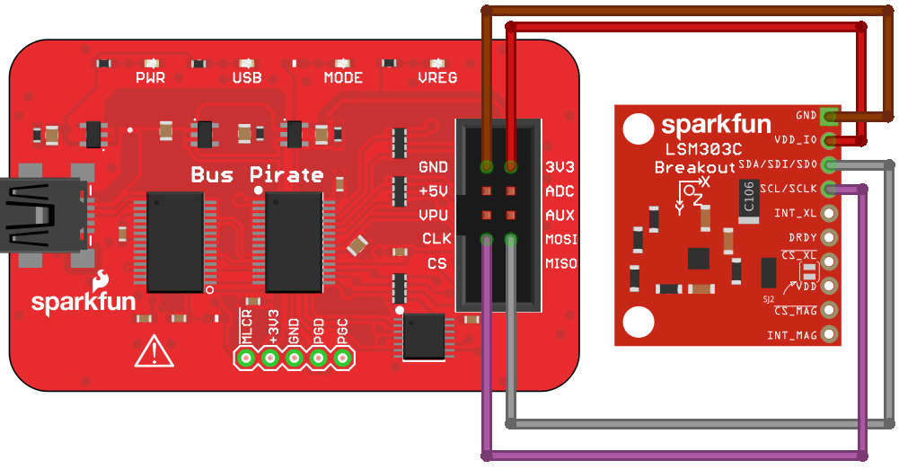
Here is a quick example of reading a register from a device on the I2C bus. I had an LSM303C Breakout laying on my desk, so I'll use it. Any I2C device will work a similar way. Here is a picture of all of the connections required to get the breakout board powered an communicating. This board runs on 3.3V, so we will power it with the red wire.
Note: By default VDD & VDD_IO on the LSM303C breakout are connected and either could have been used to power the board.
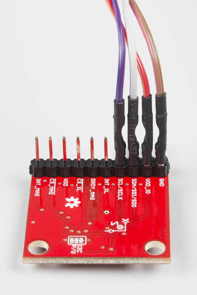
On Mac or Linux, I typically run picocom. You can use about any terminal emulator you like. I connect with a command such as picocom -b115200 /dev/tty.usbserial-AL00ESEO. The default baudrate of the Bus Pirate is 115200 baud, and the hardware I have in hand shows up at /dev/tty.usbserial-AL00ESEO. The first step is to select the correct mode. We say above from the help that m is the 'Change mode' command. This will show the 9 mode options.
HiZ>m
1. HiZ
2. 1-WIRE
3. UART
4. I2C
5. SPI
6. 2WIRE
7. 3WIRE
8. LCD
9. DIO
x. exit(without change)
We want I2C, so we will enter 4:
(1)>4
Set speed:
 1. ~5KHz
 2. ~50KHz
 3. ~100KHz
 4. ~400KHz
Let's select 400KHz mode, because we can, so why not?
(1)>4
Ready
To power the board we need to enable the power regulators with 'W' ('w' will disable):
I2C>W
Power supplies ON
At this point you might also want to enable pull-up resistors. To do so you need to connect the VPU pin to the correct voltage supply. Then 'P' will connect the resistors. The LSM303C Breakout already has pull-up resistors, so we can skip this step. We are ready to start communicating with the IC.
Let's take a look at the LSM303C datasheet to see what it expects to see on the I2C bus:
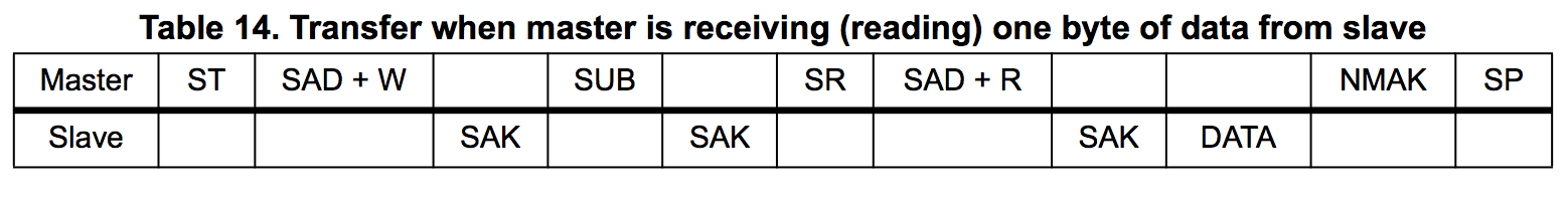
It looks like as the master we need to send a start condition then a slave address with the read/write bit clear for a write. The LSM303C should then acknowledge receipt (ACK). Next we need to send the address of the register or interest. The slave/LSM303C should ACK. Next we need to send a repeated start condition (same thing as a normal start condition), followed by the slave address with the r/w bit set to do a read. The LSM303C should respond, and we as the master don't acknowledge. The sequence ends with a stop condition.
Looks like we need more details such as the addresses. The LSM303C datasheet gives the 7-bit slave address to be 0011101b (0x1D) for the accelerometer and 0011110b (0x1E) for the magnetometer.
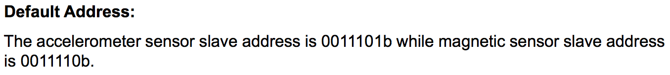
To use these addresses we need to append the read/write bit to the end. In our case if we want to read from the accelerometer we need to shift 0b0011101 left once and or that with 0x01 to indicate a read. The shift yields 0b0111010 and OR-ing that result with 1 results in 0b0111011 (0x3B). If we had OR-ed with 0x00 for a write we would have got 0b0111010 (0x3A) for the write address. Let's use a Bus Pirate macro to see if those addresses exist on the bus:
I2C>(1)
Searching I2C address space. Found devices at:
0x3A(0x1D W) 0x3B(0x1D R) 0x3C(0x1E W) 0x3D(0x1E R)
Sure enough, we can see a write address at 0x3A, and a read address at 0x3B! Now we need to know the address of a register to read from. The WHO_AM_I_A (0x0F) register always contains 0x41, so that makes an easy read to verify.

Let's put all of those addresses into Bus Pirate syntax and in the format that the LSM303C will respond to. Start condition [, write address 0x3A, register address 0x0F, repeated start condition [, read address with read command 0x3B r, and end it all with a stop condition ]. Here is how the Bus Pirate responds to that input:
I2C>[0x3a 0x0f [0x3b r]
I2C START BIT
WRITE: 0x3A ACK
WRITE: 0x0F ACK
I2C START BIT
WRITE: 0x3B ACK
READ: 0x41
NACK
I2C STOP BIT
I2C>
The Bus Pirate read 0x41, which is what that register is supposed to contain!
Other Commands
There are a lot of other commands available via the user terminal mode. Here is a quick reference to them and how they respond.
Convert base of one byte (=X)
DIO>=0x7E
0x7E = 126 = 0b01111110
Reverse one byte (|X)
DIO>|0b100110
0x64 = 100 = 0b01100100
Self-test (~) - Runs in HiZ mode only
HiZ>~
Disconnect any devices
Connect (Vpu to +5V) and (ADC to +3.3V)
Space to continue
Ctrl
AUX OK
MODE LED OK
PULLUP H OK
PULLUP L OK
VREG OK
ADC and supply
5V(5.01) OK
VPU(5.00) OK
3.3V(3.35) OK
ADC(3.43) OK
Bus high
MOSI OK
CLK OK
MISO OK
CS OK
Bus Hi-Z 0
MOSI OK
CLK OK
MISO OK
CS OK
Bus Hi-Z 1
MOSI OK
CLK OK
MISO OK
CS OK
MODE and VREG LEDs should be on!
Any key to exit
Found 0 errors.
Reset (#)
HiZ>#
RESET

Bus Pirate v3a
Firmware v5.10 (r559)  Bootloader v4.4
DEVID:0x0447 REVID:0x3046 (24FJ64GA002 B8)
http://dangerousprototypes.com
Jump to bootloader ($)
HiZ>$
Are you sure? y
BOOTLOADER
Delay (&/%)
HiZ>&
DELAY 1us
HiZ>%
DELAY 1ms
Auxiliary Pin (a/A/@)
DIO>a
AUX LOW
DIO>A
AUX HIGH
DIO>@
AUX INPUT/HI-Z, READ: 1
Set baudrate (b)
HiZ>b
Set serial port speed: (bps)
 1. 300
 2. 1200
 3. 2400
 4. 4800
 5. 9600
 6. 19200
 7. 38400
 8. 57600
 9. 115200
10. BRG raw value

(9)>9
Adjust your terminal
Space to continue
Auxiliary assignment (c/C)
HiZ>c
a/A/@ controls AUX pin
HiZ>C
a/A/@ controls CS pin
Measure ADC (d/D)
once:

1-WIRE>d
VOLTAGE PROBE: 3.33V

continuous:

DIO>D
VOLTMETER MODE
Any key to exit
VOLTAGE PROBE: 0.00V
g - 3.3V PWM on auxpin (blue wire)
DIO>g
PWM disabled
DIO>g
1KHz-4,000KHz PWM
Frequency in KHz
(50)>
Duty cycle in %
(50)>
PWM active
HiZ>=0x1010
0x10 = 16 = 0b00010000
HiZ>o
 1. HEX
 2. DEC
 3. BIN
 4. RAW
Modes:
HiZ>m
1. HiZ
2. 1-WIRE
3. UART
4. I2C
5. SPI
6. 2WIRE
7. 3WIRE
8. LCD
9. DIO
x. exit(without change)

(1)>
Resources and Going Further
Now that you have had a brief overview of the Bus Pirate, take a look at the official documentation and the Dangerous Prototypes SVN repository.