Build an Auduino Step Sequencer
 Nick Poole
Buttons and Knobs
Alright, now it's time to put together the front panel! This will be the interface that we use to adjust synth parameters and edit steps. Looking back at the code, you'll note that we have a number of analog inputs, digital inputs, and digital outputs. We can handle the analog inputs with 10k linear potentiometers. By forming a voltage divider across the potentiometer, we make it possible to dial in any voltage to the analog pin and read its position using the Arduino. The digital inputs will just be buttons to ground, since the Arduino has internal pull-up resistors. Finally, LEDs will act as our outputs.
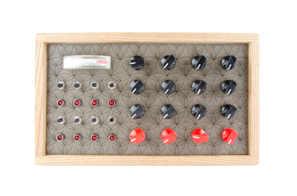
I built the front panel of my synthesizer out of chipboard, which I coated in clear enamel for rigidity. You can make it from anything you want: acrylic, wood, sheet metal, so long as it's rigid enough to hold all of the components in place. I started by just mounting all of my controls and making sure that they were all oriented correctly before wiring them up.

You'll notice there's a rectangular hole in my front panel above the step indicator lights. That's for a VU Meter that I dug up at a local surplus shop. It isn't even a VU Meter. It was apparently for indicating the operating voltage of some huge piece of equipment... anyway, I just drove it off the audio output with a diode to prevent EMF related problems and drop the line voltage into the operating range of the gauge. I won't go into any more detail about that since I'll never be able to track down a part number for you on that, and, if you go find your own, it will undoubtedly have its own special operating range.
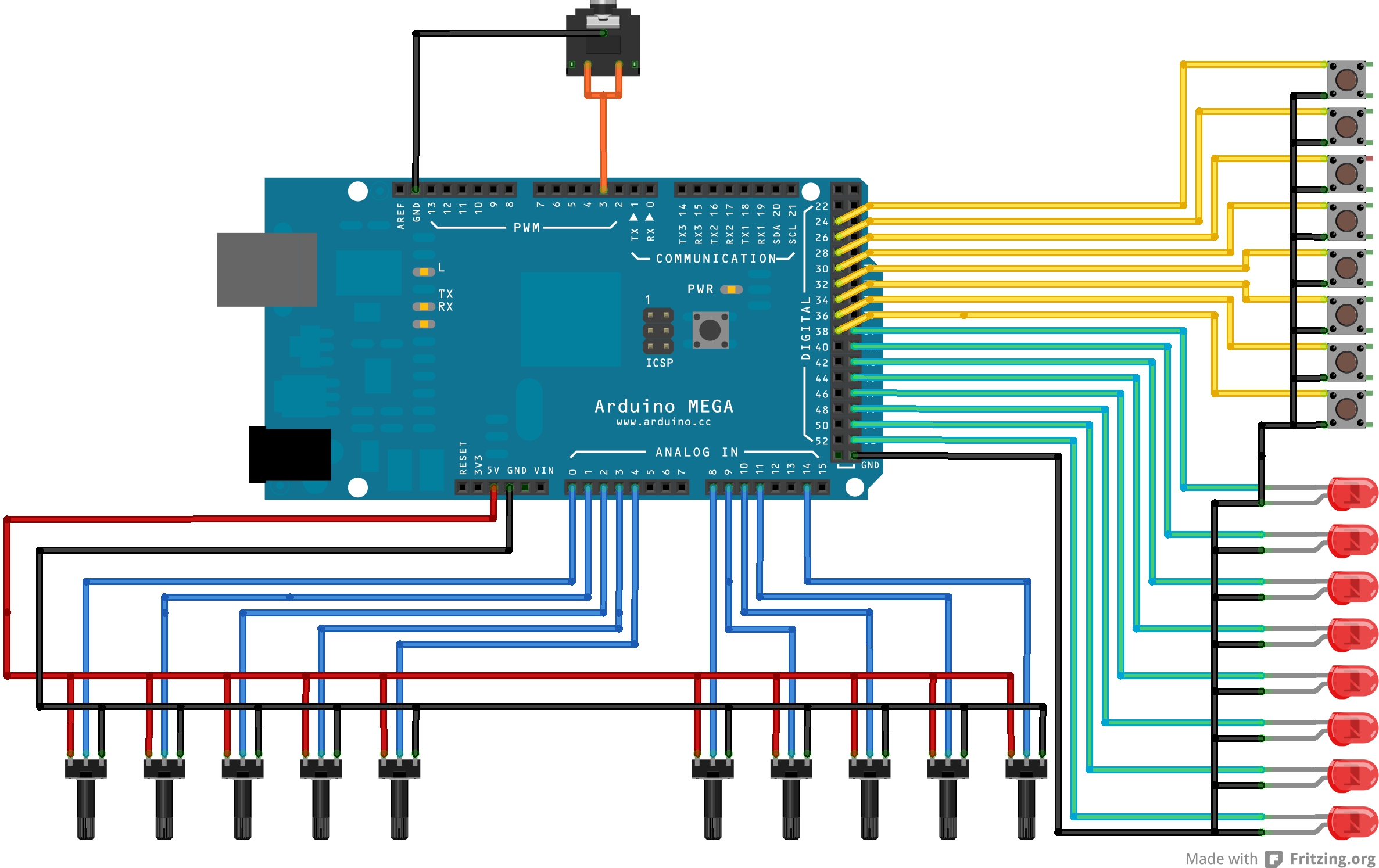
The next order of business is to wire everything. It helps to consult the code to figure out to which pin on the Arduino everything is supposed to connect. Each potentiometer gets a 5V and a GND connection. Then the center pin (the wiper) is connected to the appropriate analog input. Each LED is connected to its respective digital output as well as GND. Each button is connected to a digital input and a GND. Finally, connect the audio output to pin 13 and GND. If you're using a stereo output jack, you can tie both channels together. In this configuration, the audio jack will output 5V audio instead of standard 1V line level. Most amplifiers and headphones don't care, but just keep it in mind. I've put together the drawing below to help you wrap your head around things:
I have a bunch more potentiometers than I really need on mine because I kind of designed the panel before I knew how the synth was going to work. You could always add some filters, though, and connect them to the leftover pots.
Along with the front panel, you'll need some kind of power connection. Our Wall Adapter Power Supplies work well for that and plug directly into the Arduino. Once I stuffed everything into the enclosure, it looked like this:
And then it was time to jam...