Ardumoto Shield Hookup Guide
This Tutorial is Retired!
This tutorial covers concepts or technologies that are no longer current. It's still here for you to read and enjoy, but may not be as useful as our newest tutorials.
View the updated tutorial: Ardumoto Shield Kit Hookup Guide
 jimblom
Introduction
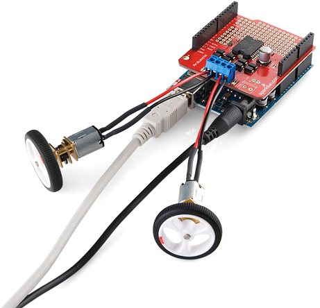
The Ardumoto Shield is an easy-to-use dual motor controller for Arduino. Combined with an Arduino, the Ardumoto makes a fantastic controller platform for RC vehicles or even small autonomous robots.
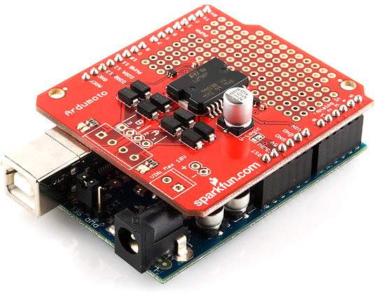
At the heart of the Ardumoto is an L298 dual full-bridge motor driver, one of our favorite motor drivers around. It's able to drive two, separate DC motors forwards and backwards at up to 2A each.
In this tutorial we'll go over some of the basics of both the Ardumoto and the L298 living on it. Digging deeper, we'll get into some assembly tips, and finish with an example Arduino sketch.
Required Tools & Materials
To follow along with this tutorial, you'll need an Ardumoto Shield and an Arduino or Arduino-compatible development board.
In addition to those, you'll also probably want a couple of DC motors to drive. The Ardumoto can control most small DC motors, like any of those in our DC motor category. Motors are also already included with many robot chassis, like the Magician or Tank Chassis.
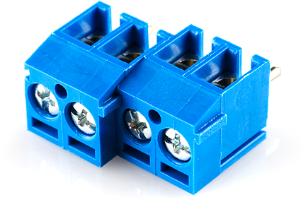
Finally, you'll need a handful of connectors to get everything wired up together. We recommend Stackable Headers to connect your Ardumoto to your Arduino. And two or three 3.5mm Screw Terminals to help connect motors to your Ardumoto.
You'll also need a few tools, including:
Suggested Reading
The Ardumoto is a great platform for first-time motor users (and experienced ones too!). There are, however, a few concepts you should be familiar with before clicking over to the next few pages. Here are some tutorials we recommend reading first:
- Motors and Selecting the Right One - Learn all about motors before learning how to control them.
- Arduino Shields -- This tutorial provides an overview of shields in general. It also contains an assembly guide for attaching headers to your shield.
- Pulse Width Modulation (PWM) -- PWM is used to control the speed of our motors.
- How to Solder -- Through Hole -- To electrically secure the connectors and headers, you'll need to solder them to your shield.
- Voltage, Current, Resistance, and Ohm's Law -- When we dive into the L298, it'll be good to know the basics of voltage and current.
Meet the L298
At the heart of the Ardumoto -- the big, black chip right in the middle -- is an L298, one of our favorite dual-channel motor drivers around. On this page, we'll give you some background information on the chip we'll be depending on to drive our motors.
But First...Why a Motor Driver?
DC motors are the easiest motors to use. They're dumb (they don't provide feedback), but they're good at spinning in one direction or the other when we tell them to. Unlike servos or steppers, DC motors don't require any special signals -- just a straight DC voltage. So why can't we just connect them directly to the Arduino?
Well, motors tend to draw a lot of current, and trying to drive a motor straight from your Arduino output pins will make your Arduino quite cross with you. The Ardumoto lets you control a whole bunch of current (good for motors) with an itty-bitty signal (good for Arduinos). Everyone's happy!
Here are some of the important features and specifications of the L298. These extend out to be the specifications of the Ardumoto as well:
Two Channels @ 2A Each
The L298 is a two-channel motor driver. That means it can individually drive up to two motors. So it's perfect for a two-wheel drive vehicle, but if you have a special, four-wheel drive platform, you might need something else (or just two L298's).
Each channel on the L298 can deliver up to 2A to the motor to which it's connected. Keep in mind, though, that the amount of current available to your motor also depends on your system's power source. Batteries are great power sources because they're mobile, and can discharge a lot of current, but high current draw also means they'll drain faster.
The Control Signals
Controlling the L298 is very easy. If you've ever blinked or dimmed an LED, you already have all the tools necessary to control the L298.
For each of the L298's channels, there are two types of input we need to send to drive a motor: direction and enable. Each of these inputs are boolean -- either high or low.
Using the direction inputs, we can control whether the motor spins clockwise or counterclockwise. The L298 actually has two direction inputs for each channel, but on the Ardumoto, as we'll show on the next page, we've merged those two inputs into one.
The enable input can be driven either high or low to make the motor spin or stop. But, with pulse-width modulation (PWM), we can actually use this input to control the speed of our motor. Just like it can be used to dim LEDs, PWM is perfect for controlling how fast our DC motor spins.
All of the control signals are limited to a maximum of 7V. Which is great, because our Arduino is only going to supply a maximum of 5V.
That covers the basics of the L298. If you're curious, or want to know more about the chip, checking out the datasheet is a good place to start.
Board Overview
Before you get your soldering iron out, or start attaching motors, it'd be best if we briefly covered the basics of the Ardumoto Shield. On this page, we'll highlight the important inputs and outputs of the shield, so you can get a better idea of how you want to assemble it later.
Pins and Connectors
Here's an annotated view of the shield, highlighting the important pins and components:
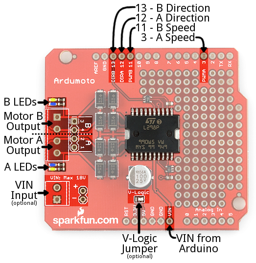
The Ardumoto Shield lays claim to four Arduino pins: 3, 11, 12, and 13. Each motor uses two pins -- one for direction, the other controls the speed.
| Arduino Pin | Ardumoto Shield Pin Label | Notes |
|---|---|---|
| 3 | PWM A | A PWM signal to control the speed of motor A. 0=off, 255=max speed. |
| 11 | PWM B | A PWM signal to control the speed of motor B. 0=off, 255=max speed. |
| 12 | DIR A | A digital signal to control the rotation direction of motor A (e.g. HIGH/LOW => CW/CCW). |
| 13 | DIR B | A digital signal to control the rotation direction of motor B (e.g. HIGH/LOW => CW/CCW). |
While the Ardumoto Shield is attached to an Arduino, these pins shouldn't be connected to anything else.
Motor Outputs
Both of the L298's motor driver outputs are broken out to the left-edge of the shield. These 2-pin outputs are broken out to two footprints: a 3.5mm-pitch screw terminal and a 0.1"-pitch header. You can use either to wire up your motor, but screw terminals make life much easier if you need to disconnect your motor. The L298 is perfect for building simple 2 wheel drive robot platforms -- connect one motor to port A and the other motor to port B.
Technically, there is no right or wrong way to connect your motor's wires to the two output pins, but to help keep things straight, we suggest connecting the red / black wire for each motor to pins 1 / 2 on port A and pin 3 / 4 on port B, respectively.
Don't worry if you swap this, the direction control of the motor will just be swapped as well.
LED Indicators
Next to each of the motor outputs are a pair of blue and yellow LEDs, which indicate the direction your motor is spinning. These are great once you get to debugging your project. They're also useful if you want to test your sketch without wiring up any motors.
Supply Voltage
The Ardumoto Shield should be powered through one of two power supply inputs. Pick one or the other:
- The barrel jack input on the Arduino.
- The VIN input on the shield
If you don't want to use the Arduino's barrel jack input, you can use the VIN input on the shield instead. This voltage input will supply both the shield and the Arduino. Like the motor outputs, this connection is broken out to both a 3.5mm screw terminal and a 0.1"-pitch header.
Do not supply power to both the Arduino barrel jack input and VIN on the shield!
Spec'ing a Power Supply
Because VIN powers both your Arduino and your motors, you need to take extra care in deciding what you'll use to power your Arduino/Ardumoto combo. Not only does VIN have to fall within the acceptable range of your Arduino (usually 6-15V), but it also has to meet the specifications of your motor.
Check the voltage and current requirements of your motor before deciding how to power your Ardumoto project. These specifications vary. The Mini Metal Gearmotors, for example, have a recommended range of 4.5-6V, but can be safely powered at up to 9V. The motors on a Magician Chassis have a recommended voltage of 4.5V, and a maximum of 6V (more may work, but it could also shorten the motor's life).
Dual-cell LiPo battery packs (7.4V nominal, 1000mAh capacity) are usually a good option if you're looking for something mobile. A 9V wall wart can work if your project is stationary. For more help picking a power supply, check out our How to Power a Project tutorial.
Assembly Tips
Before you can start using the Ardumoto Shield, you have to do a little assembly. Embrace your inner electronics technician and whip out that soldering iron! Time to turn a mish-mash of parts into a fully-functional 'duino shield!
On this page we'll go over some assembly tips. You don't have to follow these steps exactly -- assemble the shield as best fits your project's needs -- but this is good for general use of the shield.
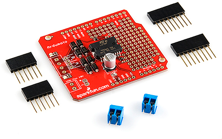
Add Screw Terminals (Optional)
If you please, you can add screw terminals to both of the motor outputs and/or the VIN input.
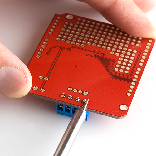
If you're adding screw terminals to the motor outputs, slide them together first:
Then insert them into the shield and solder.
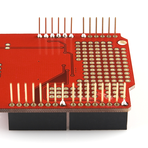
Solder the Arduino Headers
To interface the shield with your Arduino, soldering male connectors to the 28 header pins is a must. Soldering ensures a reliable physical and electrical connection. If you've never soldered before, check out our through-hole soldering tutorial.
There are usually two options for connectors when you're assembling a shield: stackable or straight. We recommend stackable headers, because it allows you to stack other shields or jumper wires on top. The smaller male headers are a good option if you're looking for lower-profile installation.
If this is your first shield assembly, we recommend reading through our shield assembly guide. There are all sorts of tricks to installing shield headers, and making them look as good and straight as possible!
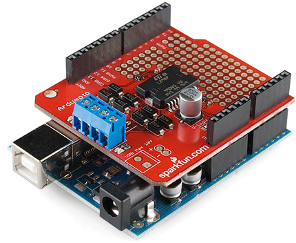
Once you're done soldering the headers, plug the shield in to make sure everything fits cozily.
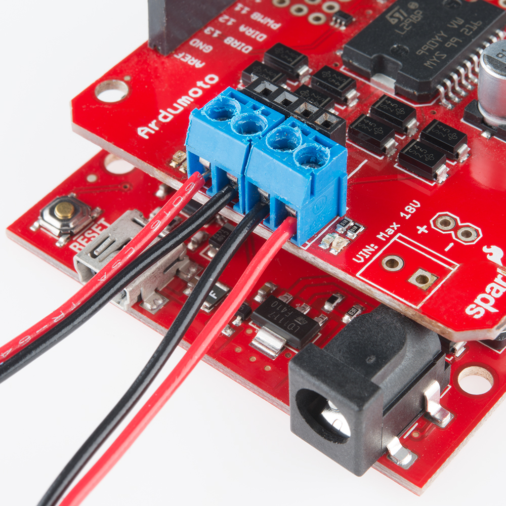
Connecting Motors
This is where the shield assembly gets very project-specific. Have you picked out which motors you'll be driving with the shield? Do you know how long the wires need to be trimmed? There's a lot to be answered here before continuing on...
Once you've figured out your motor placement, feel free to connect them to your shield. If you added screw terminals in the last step, break out your mini phillips screw driver. Otherwise, you may be soldering the motors directly to your shield.
Prototyping Area
Let's address the elephant in the room. There's almost half-a-shield that we've failed to talk about thus far. The prototyping area! These rows and columns of 0.1"-spaced plated through-holes can be used to solder in all sorts of fun components.
You could add an accelerometer to enable bump detection in your robot. Or just fill it with LEDs to make your project as blinky as possible. Or, if you don't have any plans for the area, leave it be -- maybe you'll come up with something later.
Unlike other prototyping areas you may have encountered in the past, these holes are not wired together. You don't need to do any trace-slicing, but you will need to do some soldering and wire routing.
Example Code
Controlling the Ardumoto Shield is super-easy. If you can blink LEDs, you can make the Ardumoto Shield spin its motors. Here, we'll provide a simple, expandable example sketch to show how to drive the pair of motors on the Ardumoto.
The Example Sketch
Copy and paste the example sketch below, or click the here to download it:
language:c
/* Ardumoto Example Sketch
  by: Jim Lindblom
  date: November 8, 2013
  license: Public domain. Please use, reuse, and modify this
  sketch!

  Three useful functions are defined:
    setupArdumoto() -- Setup the Ardumoto Shield pins
    driveArdumoto([motor], [direction], [speed]) -- Drive [motor]
      (0 for A, 1 for B) in [direction] (0 or 1) at a [speed]
      between 0 and 255. It will spin until told to stop.
    stopArdumoto([motor]) -- Stop driving [motor] (0 or 1).

  setupArdumoto() is called in the setup().
  The loop() demonstrates use of the motor driving functions.
*/

// Clockwise and counter-clockwise definitions.
// Depending on how you wired your motors, you may need to swap.
#define CW  0
#define CCW 1

// Motor definitions to make life easier:
#define MOTOR_A 0
#define MOTOR_B 1

// Pin Assignments //
// Don't change these! These pins are statically defined by shield layout
const byte PWMA = 3;  // PWM control (speed) for motor A
const byte PWMB = 11; // PWM control (speed) for motor B
const byte DIRA = 12; // Direction control for motor A
const byte DIRB = 13; // Direction control for motor B

void setup()
{
  setupArdumoto(); // Set all pins as outputs
}

void loop()
{
  // Drive motor A (and only motor A) at various speeds, then stop.
  driveArdumoto(MOTOR_A, CCW, 255); // Set motor A to CCW at max
  delay(1000);  // Motor A will spin as set for 1 second
  driveArdumoto(MOTOR_A, CW, 127);  // Set motor A to CW at half
  delay(1000);  // Motor A will keep trucking for 1 second
  stopArdumoto(MOTOR_A);  // STOP motor A

  // Drive motor B (and only motor B) at various speeds, then stop.
  driveArdumoto(MOTOR_B, CCW, 255); // Set motor B to CCW at max
  delay(1000);  // Motor B will spin as set for 1 second
  driveArdumoto(MOTOR_B, CW, 127);  // Set motor B to CW at half
  delay(1000);  // Motor B will keep trucking for 1 second
  stopArdumoto(MOTOR_B);  // STOP motor B

  // Now spin both!
  driveArdumoto(MOTOR_A, CW, 255);  // Motor A at max speed.
  driveArdumoto(MOTOR_B, CW, 255);  // Motor B at max speed.
  delay(1000);  // Drive forward for a second
  // Now go backwards at half that speed:
  driveArdumoto(MOTOR_A, CCW, 127);  // Motor A at max speed.
  driveArdumoto(MOTOR_B, CCW, 127);  // Motor B at max speed.
}

// driveArdumoto drives 'motor' in 'dir' direction at 'spd' speed
void driveArdumoto(byte motor, byte dir, byte spd)
{
  if (motor == MOTOR_A)
  {
    digitalWrite(DIRA, dir);
    analogWrite(PWMA, spd);
  }
  else if (motor == MOTOR_B)
  {
    digitalWrite(DIRB, dir);
    analogWrite(PWMB, spd);
  }
}

// stopArdumoto makes a motor stop
void stopArdumoto(byte motor)
{
  driveArdumoto(motor, 0, 0);
}

// setupArdumoto initialize all pins
void setupArdumoto()
{
  // All pins should be setup as outputs:
  pinMode(PWMA, OUTPUT);
  pinMode(PWMB, OUTPUT);
  pinMode(DIRA, OUTPUT);
  pinMode(DIRB, OUTPUT);

  // Initialize all pins as low:
  digitalWrite(PWMA, LOW);
  digitalWrite(PWMB, LOW);
  digitalWrite(DIRA, LOW);
  digitalWrite(DIRB, LOW);
}
Then upload to your Arduino and watch your motors spin! If you want to dig really deep into the sketch, check out the comments.
Explaining the Sketch
For each motor there are two mechanisms we can control -- the direction of rotation and the speed. Each of those mechanisms is controlled by one pin on the Arduino.
Controlling Rotation Direction
We can only spin the motor in two directions -- clockwise or counter-clockwise -- so we only need two values -- 0 or 1 -- to control that from the Arduino. We can simply digitalWrite either of the direction pins (pin 12 for motor A, pin 13 for motor B) HIGH or LOW to go forward or backward.
For example, if you want motor A to spin clockwise, you simply need to digitalWrite pin 12 LOW:
language:c
digitalWrite(12, LOW);  // Motor A will spin clockwise
To make it spin the other way, write the pin HIGH.
language:c
digitalWrite(12, HIGH);  // Motor A will spin counter-clockwise
(Note: The rotation direction depends on how you wired the motor to your shield. If you swapped the red and black wires, the motor will spin opposite of how we've described here.)
Speeding
To control the speed of a motor we need to analogWrite to the PWM pins (pin 3 for motor A, pin 11 for motor B). A higher analogWrite value means a faster spin. Writing the pin LOW (or 0) will stop the motor.
| PWM value | Motor Spin Speed |
|---|---|
| 0 | Off (Stop) |
| 127 | Half speed |
| 255 | Full speed |
If we want to turn motor A up to maximum speed, this is all we need:
language:c
analogWrite(3, 255);  // Motor A at max speed
After that line of code is executed, the motor will spin until stopped. To stop the motor, replace 255 with 0:
language:c
analogWrite(3, 0);  // Stop motor A
Don't forget to set your direction before spinning your motor!
Resources and Going Further
Resources
- Ardumoto Shield Schematic -- A PDF of the shield's schematic.
- Ardumoto Shield Eagle Files -- The PCB design files.
- L298 Data Sheet -- Everything you could ever want to know about the L298 dual motor driver.
Going Further
- Getting Started with the RedBot -- If you're looking for a complete, beginner-level robotics platform, check out the RedBot Kit. It's Arduino-compatible, and the RedBot Mainboard has a motor driver built into it, so you don't even need an Ardumoto Shield.
- Getting Started with the MiniMoto -- The MiniMoto is a more advanced, digitally-controlled, low-voltage DC motor driver.
- How to Power a Project -- Batteries? Wall-warts? Solar? If you're not sure how to power your Ardumoto Shield based project, take a trip over to this tutorial.
- HUB-ee Buggy Project - Build your own buggy using an Ardumoto shield.