Uh-Oh Battery Level Indicator Hookup Guide
Contributors:
 Toni_K
Toni_K 
Hookup Example
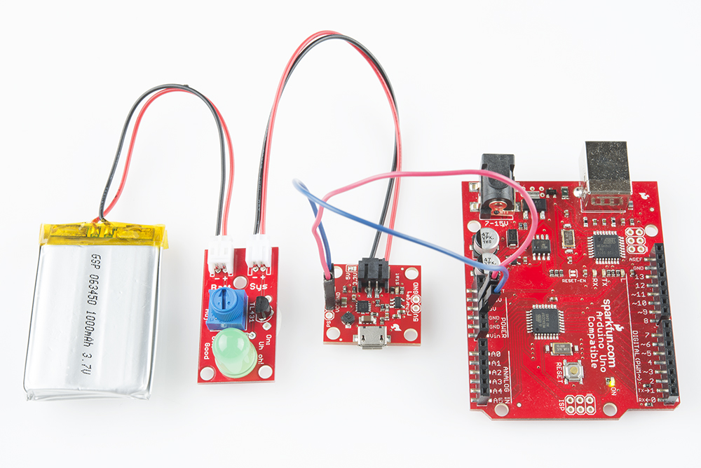
Once you have soldered your kit together, it's time to start monitoring your battery levels. For this example, we will be hooking up the indicator to a 3.7V lipo battery that is powering an Arduino Uno. We will also be including a Power Cell- LiPo Charger/Booster in the circuit, to ensure that we can recharge the battery when it reaches the low voltage limit.
Connections:
Uno → PowerCell Charger
- 5V → VCC
- GND → GND
PowerCell Charger → Uh-Oh Indicator
- PowerCell + → Sys +
- PowerCell - → Sys -
Uh-Oh Indicator → Battery
- The JST connector on the battery is notched and corresponds to the notch on the Uh-Oh Indicator.
Here is a Fritzing diagram showing the actual connections between the Uno, the PowerCell, the Uh-Oh indicator, and the battery.
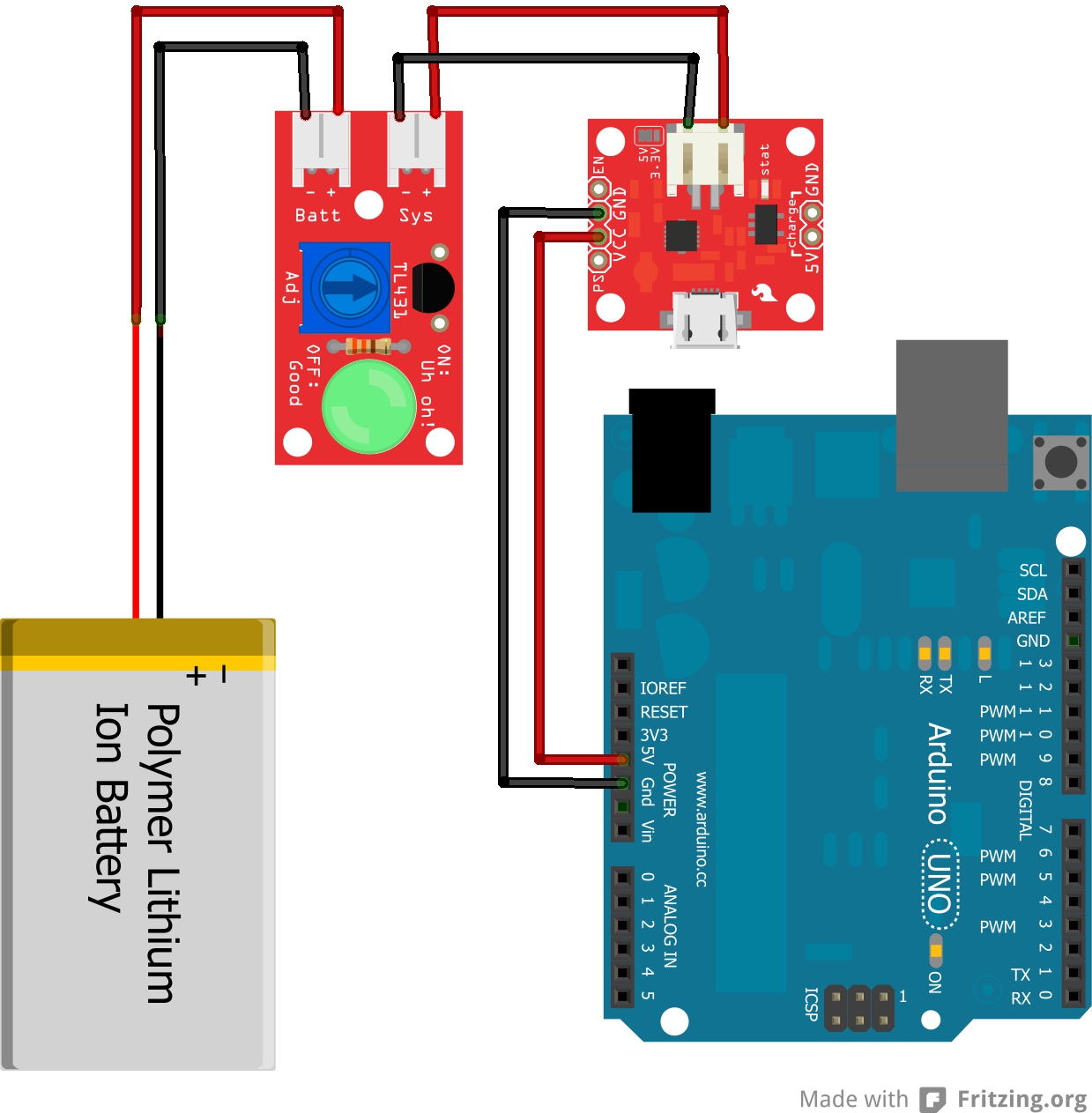
Once you have everything hooked up, you will need to adjust the trimpot on the Uh-Oh indicator board to the voltage at which you would like to be notified.