Teensy Human Motion and Presence Alarm Tutorial

Hookup and Assembly
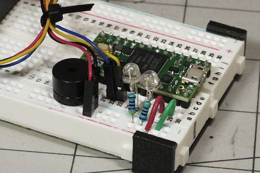
Solder header pins to your Teensy 4.0 and plug into the end of the breadboard. Jumper Ground and 3.3V from the Teensy to the rails as shown. Solder resistors to the negative leg of each LED (typically shorter, metal inside points toward positive). Connect the negative/resistor of each LED to the breadboard ground rail, and the positive to Teensy pin 22 for green (motion detected) and 21 for red (presence detected). Connect the positive speaker lead to Teensy pin 14 and the negative to the ground rail for sound output.
Push the Qwiic cable plug into either connector socket on the breakout board. Connect the Qwiic jumper wires to: black — ground rail, red — 3.3V rail, yellow (SCL) — Teensy pin 19, blue (SDA) — Teensy pin 18 via the breadboard.
Print the fixtures and slide both onto the breadboard. Place the SparkFun sensor breakout onto the fixture’s nubs. The full-sized version is oriented facing outwards as shown in the first image on this article. The holder is reversed for the miniature version, with the sensor itself pointing into (and through) the fixture, as shown in the last image in this article.