Spectrum Shield Hookup Guide (v2)
 Toni_K, santaimpersonator
Hardware Overview
Audio Connections
Audio Jacks
The Spectrum Shield contains two stereo audio jacks on the board. The first audio jack, is the input jack (labeled Input). This allows users to input audio from any device -- such as an MP3 player, or cellular phone -- using a basic audio cable. This connection does not have to be used, as there is another option for adding audio input, at the "Audio In" headers, described below.
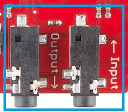
The second audio jack is the audio output, labeled Output. This jack allows you to pass the audio back out to a speaker or other audio system, while the sound levels are being processed by the Spectrum Analyzer ICs. (*Technically, both audio jacks and the audio header are all tied together and can be used as either an input or output.)
Audio In Header
For some projects, you may not be piping audio from a pre-processed source such as a cell phone. For users who want to use things like a MEMS Mic Breakout or the Sound Detector as an audio source, there are three header pins that provide an alternative connection method to your shield.
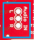
These pins are as follows:
- L = Left Audio Input
- G = Ground Audio Input
- R = Right Audio Input
With both the left and right inputs, you can use stereo devices on these headers. The signals also passes through to the Input and Output audio jacks.
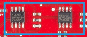
MSGEQ7 ICs
The real power of this shield comes from the two MSGEQ7 ICs on the board. These are CMOS chips, which are seven band graphic equalizers.
Upon receiving an audio signal in, these ICs split the the spectrum into seven bands, splitting it at the following frequencies:
- 63Hz
- 160Hz
- 400Hz
- 1kHz
- 2.5kHz
- 6.25kHz
- 16kHZ
For the visual learners, here's the frequency graph from the MSGEQ7 datasheet:
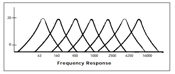
Once the spectrum has been split into these ranges, each band is peak detected and multiplexed. The DC output is a representation of the amplitude of each frequency band. Using the strobe and reset pins on the ICs allows the user to select the DC peak output.
Shield Connections
There are 4 main pins that the Arduino/RedBoard or other microcontroller connect to the Spectrum Shield.
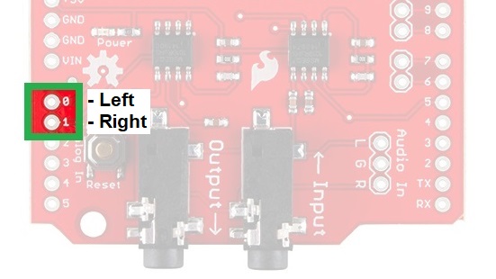
Analog Pins -
There are two analog pins connected to the MSGEQ7 ICs. A0 is the DC analog output from the first IC for the left audio channel, while A1 is the DC analog output from the second, right audio channel.
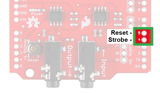
Control Pins -
The control pins connect to the Strobe and Reset pins on the MSGEQ7; D4 and D5, respectively. In order to enable the Strobe pin, you must pull the Reset pin LOW. To reset the entire multiplexer, pull the Reset pin HIGH.
The Strobe pin, once activated, cycles through each of the channels. After the initial pulse, it starts at 63Hz, pulses each channel until 16kHz, and then repeats, starting back at 63Hz. The DC output for each channel will follow the Strobe pulse.
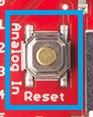
Reset Button
The reset button allows you to reset your Arduino/RedBoard while the shield is inserted. Holding the reset button will pull the reset pin of the ATMega328 (or other microcontroller) low, allowing a system reset. This will restart any sketches currently running on the microcontroller.