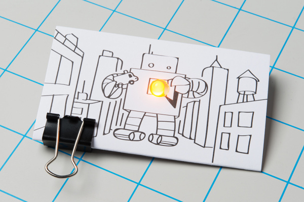
SparkFun Paper Circuit Kits
Introduction
Design and build time: 5-10 minutes
Welcome to the world of paper circuits - creating electronic projects directly on paper using simple components. This guide will walk you through building a simple circuit using copper tape, a 5mm LED, and a 3V coin cell battery.
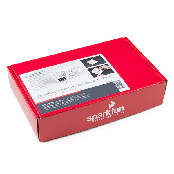
SparkFun offers two kits designed specifically for this paper circuit project. The main difference between the two kits is that the Classroom Pack includes batteries, four LED color options, and some spare parts. If using the SparkFun Paper Circuits Kit, you will need to provide or purchase your own 3V CR2032 20mm coin cell battery to follow along and complete the project.
SparkFun Paper Circuits Classroom Pack
KIT-15818Required Materials and Tools
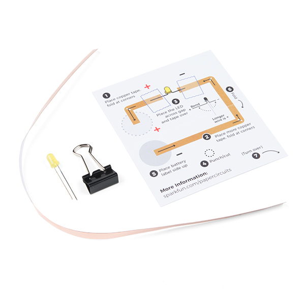
In your paper circuits kit, you will find a plastic bag that includes:
- Printed Paper Circuit Template
- 12" Piece of 5mm Copper Tape
- Yellow 5mm LED
- Binder Clip
You Will Also Need:
- 3V CR2032 Coin Cell Battery (Included in the Classroom Pack)
- Scissors
- Hole Punch
- Clear Tape
- Decorating Supplies (markers, pens, crayons) If You'd Like to Color In the Finished Project
Downloadable Templates
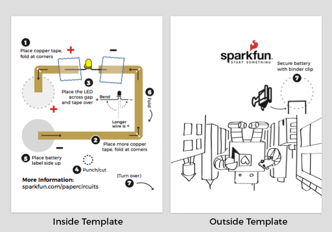
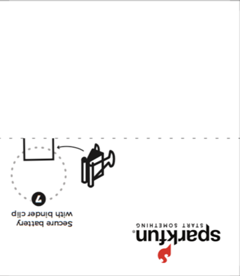
Your kit includes the following printed template. If you would like to choose a different template or make more projects, you can also download and print a PDF.
Right-click the template's image or link, and choose “Save Link As” to download the it to your computer. Each file has the circuit template on one side and a design on the other. Print on 8 ½” x 11” cardstock paper and cut out individual template (6 total per print). You will only need one to make the project.
 |
 |
Suggested Reading
If you are brand new to working with electronics, here’s some helpful reading to check out:
What is a Circuit?
Light-Emitting Diodes (LEDs)
The Great Big Guide to Paper Circuits
Create Copper Traces
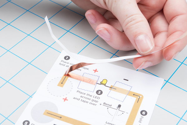
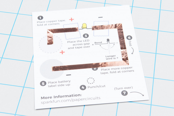
Time to create a path for our electricity to flow through our circuit. In this project, we will use copper tape wiring that connects each part of the circuit. Each template has numbered icons to help guide you in constructing the different parts of the circuit.
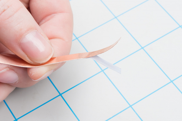
Take a look at the template and find the circle marked 1 (i.e. ①). Peel away a few inches of the paper backing from the copper tape and stick down along the shaded line to cover it.
 |
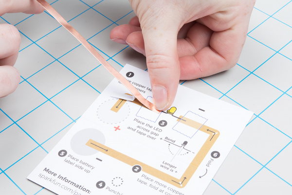 |
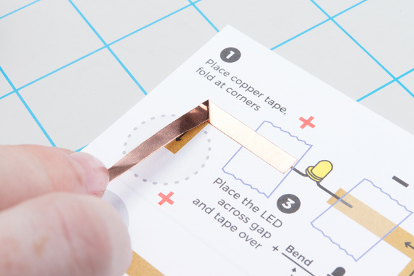
This template includes a few turns - to keep a solid connection of copper around corners, we’ll be using a folding technique to press the tape into shape. Start by sticking the copper tape down until you reach the corner, then fold the tape backward on itself. Use a fingernail or pen to give it a good crease at the edge.
Then carefully move the tape down around the corner - you should see the fold forming - and press down flat against the paper. The neatness of the fold doesn’t matter that much, it will be covered by your pop up in the end.
Corners got you confused? Watch how it is done here (watch full screen to see the process a little better):
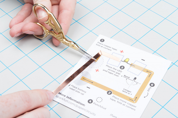
Finally, cut the tape when you reach the end of the printed line.
Repeat this process starting at the line marked 2 (i.e. ②).
Now we are done creating our copper tape paths. If you have extra tape, you can discard or save for another project.
Prepare and Place LED
Now that we've created the path for electricity to follow in the circuit, it's time to add a light-emitting diode (LED) that will turn on when we power the project. Look for the circle marked 3 (i.e. ③) and the yellow LED illustration for where to place it on the template.
LEDs
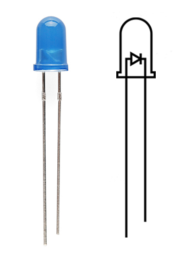
The template has an LED symbol on it which shows its wires - let’s check it out. LEDs are polarized, which means they need to be connected in a certain orientation to function. The LED has two wires coming out of its colored bulb - notice one is longer than the other - this is the positive (+) side of the LED. The shorter side is the negative (-). We will connect these on the + and - sides of our copper tape paths. There is also a flat side on the bulb itself; this is the negative side.
Bending the LED
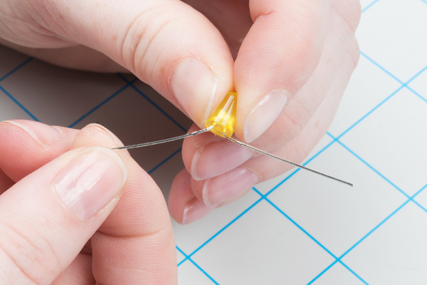
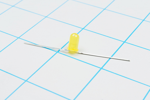
We will need to do a little preparation in order for the LED to lay flat in our circuit. Using your fingers (or pliers), bend the longer wire (also known as its ‘leg’) of the LED flat. Be careful not to break the wire by bending back and forth over the same joint too many times.
 |
 |
Next, bend the shorter (-) leg of the LED flat as shown.
Once all bending is complete, place the LED on a table or flat surface to make sure it sits flat and upright. If not, make any adjustments now.
Tape Down LED
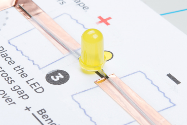
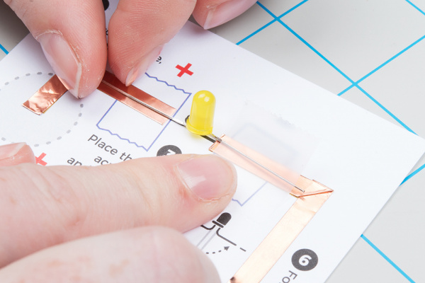
Next, line up the positive leg of the LED with the copper tape marked + and the negative with -. Use clear tape over the leads to hold down to the copper. If you have trouble telling the sides apart, check the base of the LED bulb - the flat edge is the negative (-) side.
 |
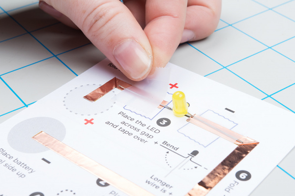 |
The connection between the LED and copper tape should look like the image below.
Punch Hole
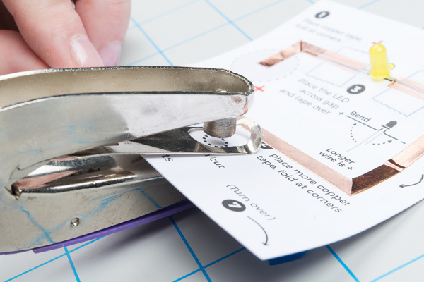
Before finishing the project, punch a hole for the LED to go through. You can use a hole punch or carefully cut with scissors.
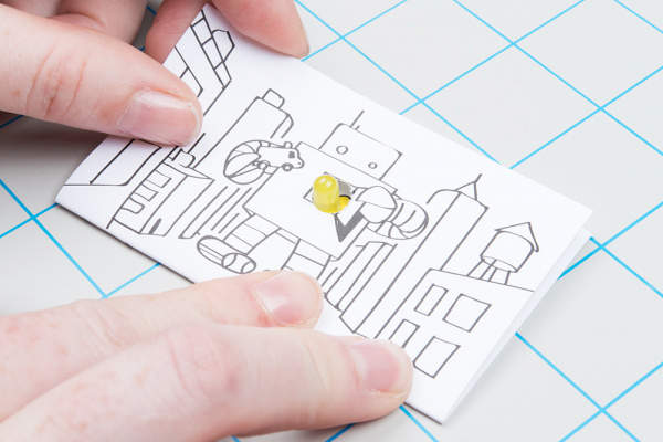
Depending on how centered you placed the LED over the gap in the copper tape, you may need to slide or slightly move it. Simply peel up the clear tape and adjust to center the LED in the hole. Then secure with some new tape. Fold the card over for a preview of where the LED will shine through on the template's design.
Insert Battery
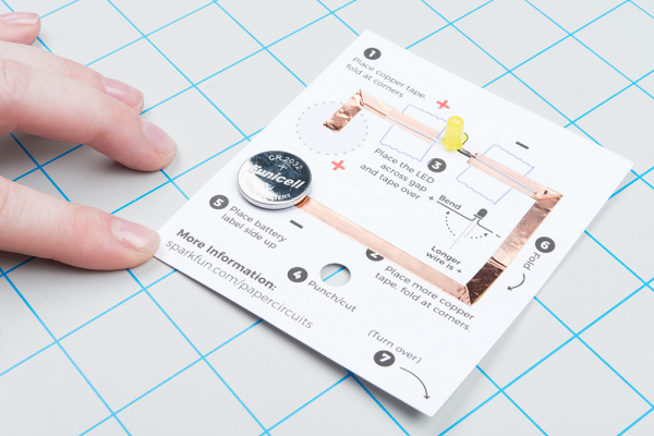
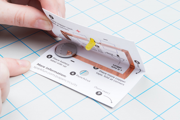
Once all the components are installed, it’s time to test our circuit by adding a battery. Place the battery inside the circle marked - with the label (marked + or with the battery name) facing up.
Carefully fold along the dotted line so that the copper tape inside the + circle rests on top of your battery, making a connection. You should see your LED light up once the copper tape touches the battery. Flip your project over and push the LED through the hole you punched to see it shine through the design.
 |
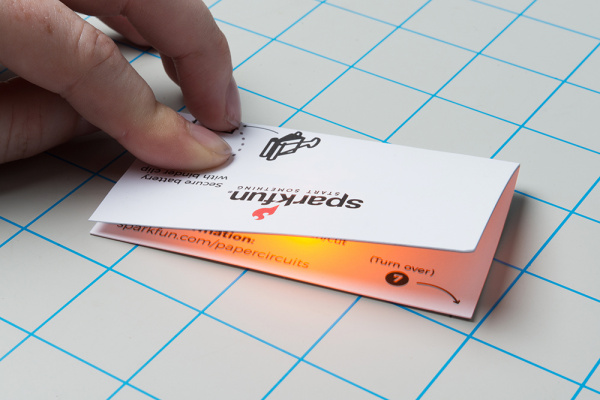 |
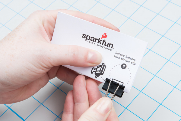
Secure the battery in the project using a binder clip. If you don't have a binder clip, a large paper clip can also work.
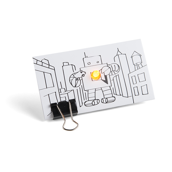
Enjoy your completed paper circuit!
Troubleshooting
- If Your LED Isn’t Lighting Up - check the tape connections. Use your nails or a pencil to make sure the LED’s wires are being held down to the copper tape and making contact.
- Check the Wires of the LED - double check that they weren’t accidentally broken while bending them or if the LED is installed with the + side to - side.
- Check the Battery - Make sure it is sandwiched firmly between the top and bottom copper tape lines and that the top copper is not accidentally touching the bottom of the battery.
Decorate and Customize
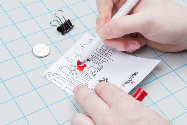
Decorate your project by coloring in the design or adding stickers. You can also make it a wearable badge by adding an adhesive pin to the back of the design. To make it easier to color on the paper, unclip the binder clip and remove the battery so the paper will lay flat on a table.
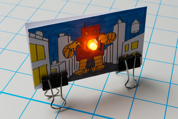
If you have a spare binder clip, attach one to the other edge of the paper to create a stand for your artwork.
You can also attach a magnet to create a fridge decoration or a pin pack to wear your project around.
Resources and Going Further
For more information, check out the resources below:
- Paper Circuit Templates
- SFE Product Showcase: SparkFun Paper Circuits
Need some inspiration for your next project? Here are some additional paper circuit projects to try out:
