SparkFun Absolute Digital Barometer - LPS28DFW (Qwiic) Hookup Guide
Arduino Examples
Now let's take a closer look at a few of the examples included in the LPS28DFW Arduino Library.
Example 1 - Basic Readings
The first example covers the basics of polling the LPS28DFW for pressure and temperature data over I2C. Open the example by navigating to File > Examples > SparkFun LPS28DFW Arduino Library > Example1_BasicReadings. Select your Board and Port and click the Upload button. Once upload completes, open the serial monitor with the baud set to 115200 and watch pressure and temperature data print out.
The code assumes the sensor uses the default I2C address so if you have adjusted the ADR jumper to switch to the alternate address, comment/uncomment the line with the correct value listed:
language:c
uint8_t i2cAddress = LPS28DFW_I2C_ADDRESS_DEFAULT; // 0x5C
//uint8_t i2cAddress = LPS28DFW_I2C_ADDRESS_SECONDARY; // 0x5D
The example attempts to initialize the sensor with default settings in I2C at the specified address. If it cannot initialize properly, the code prints out an error in over serial:
language:c
while(pressureSensor.begin(i2cAddress) != LPS28DFW_OK)
    {
        // Not connected, inform user
        Serial.println("Error: LPS28DFW not connected, check wiring and I2C address!");

        // Wait a bit to see if connection is established
        delay(1000);
    }
If you see this error, double check the sensor is connected properly and set to the correct I2C address and reset the development board or re-upload the code.
The main loop gets temperature and pressure data measurements from the sensor every second:
language:c
{
    // Get measurements from the sensor. This must be called before accessing
    // the pressure data, otherwise it will never update
    pressureSensor.getSensorData();

    // Print temperature and pressure
    Serial.print("Temperature (C): ");
    Serial.print(pressureSensor.data.heat.deg_c);
    Serial.print("\t\t");
    Serial.print("Pressure (hPa): ");
    Serial.println(pressureSensor.data.pressure.hpa);

    // Only print every second
    delay(1000);
}
Try moving the sensor up and down to see the pressure data change.
Example 3 - Interrupts
Example 3 shows how to set up and use data ready interrupts triggered by the sensor. The code defaults to use D2 as the interrupt pin on a connected development board. If your board does not support external interrupts on D2, adjust this line:
language:c
int interruptPin = 2
If you're not sure which pins on your development board support external interrupts, this reference page lists usable digital pins for most common Arduino development boards.
After initializing the LPS28DFW, the code sets the ODR to 1Hz, configures the interrupt pin to operate in Data Ready mode and attaches the interrupt to the pin defined above (D2:
language:c
ps28dfw_md_t modeConfig =
    {
        .fs  = LPS28DFW_1260hPa,    // Full scale range
        .odr = LPS28DFW_1Hz,        // Output data rate
        .avg = LPS28DFW_4_AVG,      // Average filter
        .lpf = LPS28DFW_LPF_DISABLE // Low-pass filter
    };
    pressureSensor.setModeConfig(&modeConfig);

    // Configure the LPS28DFW interrupt pin mode
    lps28dfw_int_mode_t intMode =
    {
        .int_latched  = 0, // Latching mode (not including data ready condition)
        .active_low   = 1, // Signal polarity
        .drdy_latched = 0  // Latching mode (data ready condition only)
    };
    pressureSensor.setInterruptMode(&intMode);

    // Configure the LPS28DFW to trigger interrupts when measurements finish
    lps28dfw_pin_int_route_t intRoute =
    {
        .drdy_pres = 1, // Trigger interrupts when measurements finish
        .fifo_th   = 0, // Trigger interrupts when FIFO threshold is reached
        .fifo_ovr  = 0, // Trigger interrupts when FIFO overrun occurs
        .fifo_full = 0  // Trigger interrupts when FIFO is full
    };
    pressureSensor.enableInterrupts(&intRoute);

    // Setup interrupt handler
    attachInterrupt(digitalPinToInterrupt(interruptPin), lps28dfwInterruptHandler, RISING);
}
The main loop waits for a Data Ready interrupt event to occur and then prints out the data from the sensor over serial.
Example 5 - Reference Mode
Example 5 demonstrates how to set and use reference measurements to trigger interrupts from the LPS28DFW. Reference mode allows you to store a pressure value as a reference and then monitor the sensor's output to trigger an interrupt if it goes above or below the threshold value by a specified amount.
The reference value register is READ only so we cannot manually set the threshold value in the code. Instead, the code waits for the user to input they are ready to set the threshold value and then enter any key to trigger the event.
The code sets the over and under pressure thresholds to 1hPa above/below the stored reference pressure. If you want to adjust it, change the settings here:
language:c
lps28dfw_int_th_md_t thresholdMode =
    {
        .threshold = 16, // Threshold above/below the reference pressure (eg. 16 = 1hPa in 1260hPa range)
        .over_th = true, // Enable the "over pressure" interrupt condition
        .under_th = true // Enable the "under pressure" interrupt condition
    };
    pressureSensor.setThresholdMode(&thresholdMode);
Note, the threshold value must be set in multiples of 16 when in Mode 1 (260-1260hPa) and multiples of 8 when in Mode 2 (260-4060hPa). For example, to set the pressure threshold to above/below 1hPa, set the .threshold to 16.
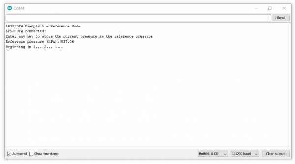
After uploading, open the serial monitor with the baud set to 115200 and get the sensor ready to take the threshold measurement. Wait for the prompt and press any key to set the value. If successful, you should see the serial printout below:
Once the threshold is set, the main loop prints out temperature and pressure data and waits for an interrupt event to trigger if the pressure readings go above or below the threshold pressure by 1hPa.
