Serial Communication
Wiring and Hardware
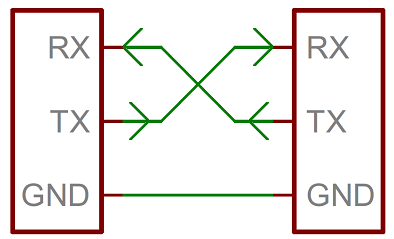
A serial bus consists of just two wires - one for sending data and another for receiving. As such, serial devices should have two serial pins: the receiver, RX, and the transmitter, TX.
It's important to note that those RX and TX labels are with respect to the device itself. So the RX from one device should go to the TX of the other, and vice-versa. It's weird if you're used to hooking up VCC to VCC, GND to GND, MOSI to MOSI, etc., but it makes sense if you think about it. The transmitter should be talking to the receiver, not to another transmitter.
A serial interface where both devices may send and receive data is either full-duplex or half-duplex. Full-duplex means both devices can send and receive simultaneously. Half-duplex communication means serial devices must take turns sending and receiving.
Some serial busses might get away with just a single connection between a sending and receiving device. For example, our Serial Enabled LCDs are all ears and don't really have any data to relay back to the controlling device. This is what's known as simplex serial communication. All you need is a single wire from the master device's TX to the listener's RX line.
Hardware Implementation
We've covered asynchronous serial from a conceptual side. We know which wires we need. But how is serial communication actually implemented at a signal level? In a variety of ways, actually. There are all sorts of standards for serial signaling. Let's look at a couple of the more popular hardware implementations of serial: logic-level (TTL) and RS-232.
When microcontrollers and other low-level ICs communicate serially they usually do so at a TTL (transistor-transistor logic) level. TTL serial signals exist between a microcontroller's voltage supply range - usually 0V to 3.3V or 5V. A signal at the VCC level (3.3V, 5V, etc.) indicates either an idle line, a bit of value 1, or a stop bit. A 0V (GND) signal represents either a start bit or a data bit of value 0.
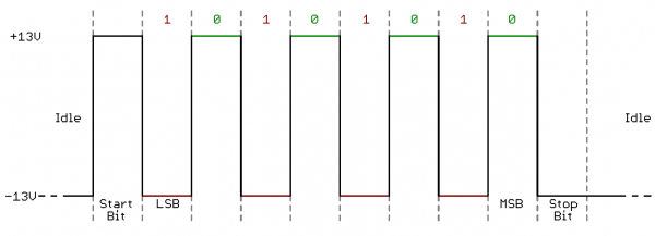
RS-232, which can be found on some of the more ancient computers and peripherals, is like TTL serial flipped on its head. RS-232 signals usually range between -13V and 13V, though the spec allows for anything from +/- 3V to +/- 25V. On these signals a low voltage (-5V, -13V, etc.) indicates either the idle line, a stop bit, or a data bit of value 1. A high RS-232 signal means either a start bit, or a 0-value data bit. That's kind of the opposite of TTL serial.
Between the two serial signal standards, TTL is much easier to implement into embedded circuits. However the low voltage levels are more susceptible to losses across long transmission lines. RS-232, or more complex standards like RS-485, are better suited to long range serial transmissions.
When you're connecting two serial devices together, it's important to make sure their signal voltages match up. You can't directly interface a TTL serial device with an RS-232 bus. You'll have to shift those signals!
Continuing on, we'll explore the tool microcontrollers use to convert their data on a parallel bus to and from a serial interface. UARTs!


