Rotary Dial Kit Assembly Guide
 Nick Poole
Hardware Assembly
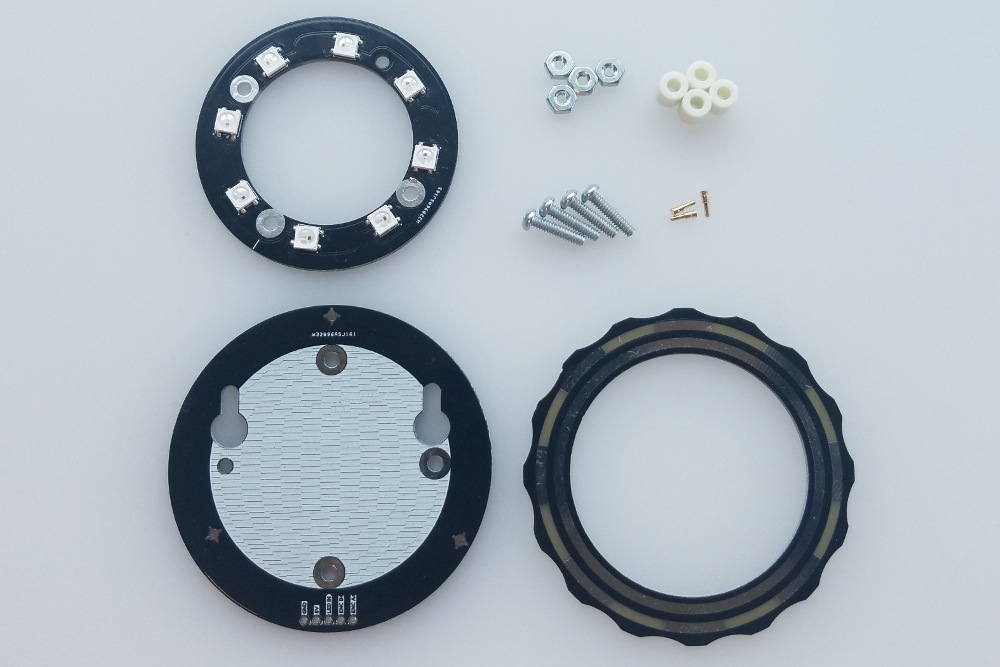
Step 1 - Count Your Parts!
Make sure you have everything that you need. The kit includes three PCBs, three pogo pins, four 4-40 bolts, four 4-40 nuts and four 1/4" standoffs.
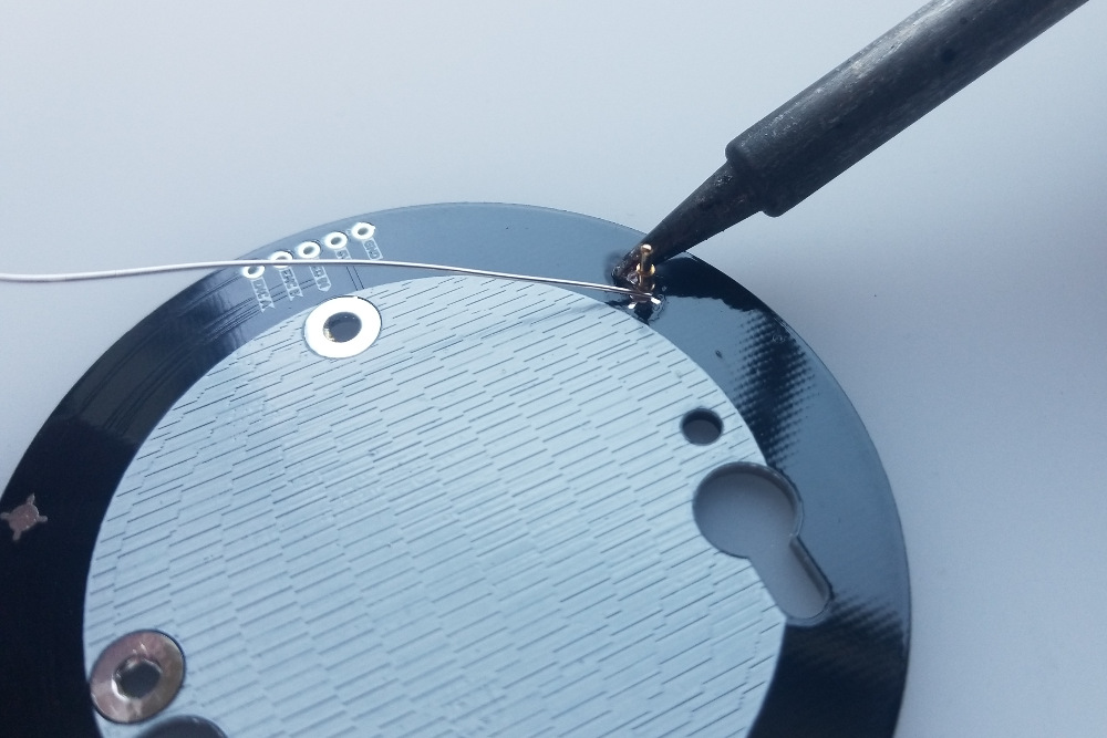
Step 2 - Solder the Pogo Pins
The trickiest part of the assembly will be soldering these pins. It's not too tough, though, so let's get it out of the way now! Start off by applying some flux to each pad, if you have it.
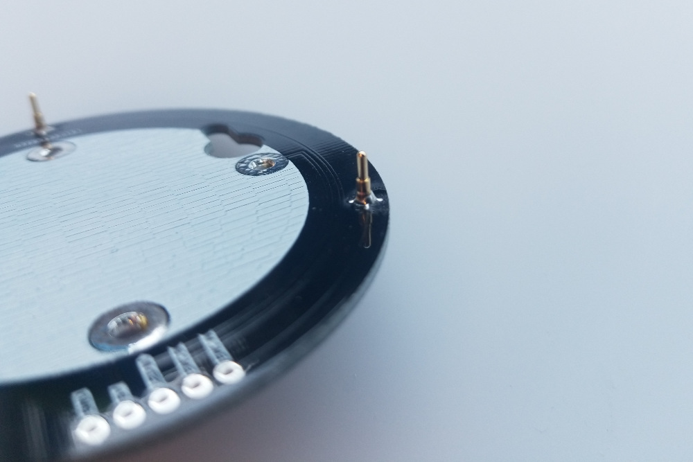
Then place a pogo pin on it's pad and center it as best you can. Don't worry too much about it because it will self-center if you add enough solder. Very carefully apply solder to the pad and allow it to flow to the pin. Add enough solder so that there is a rounded pool around the base of the pin. Once you have a small blob of solder, pull the iron away swiftly and smoothly, careful not to knock over the pogo pin. The surface tension of the still-molten solder should drag the pogo pin to the center of the pad.
Check to make sure that the pin is aligned vertically. It doesn't need to be perfectly perpendicular to the board, but it should be sticking relatively straight up. You may need to grab the pin with some tweezers, reheat the solder, and press it down onto the pad to get it aligned.
Repeat this process for each pin.
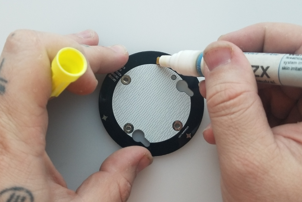
Step 3 - Add Some Solder to the Standoff Holes
The bolts that hold the assembly together are also the signal route for the RGB LEDs on the retainer ring, so it's important to create a good electrical connection. To aid in this, add a little bit of solder to the face of each standoff hole on the back of the base board and the front of the retainer board. Make sure not to overdo it and make the hole too tight for the bolt to go through. The goal is to make a little bump for the nut or the head of the bolt to tighten against.

Step 4 - Build Your Sandwich!
Now it's time to stack everything together! There are probably a lot of ways to accomplish this, but this is the way I find easiest.
Start by putting the 4-40 bolts through the front of the retainer ring (the board with the LEDs on it) so that the LEDs are on the opposite side from the head of the bolts. Now set this aside and place your base board with the pogo pins facing up.
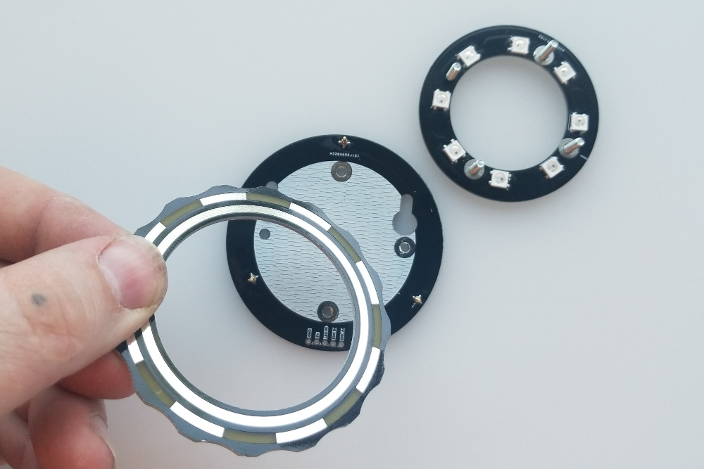
Carefully place a nylon standoff over each of the four standoff holes and place the ring pcb with the shiny side facing up and the tracks facing down onto the pogo pins.
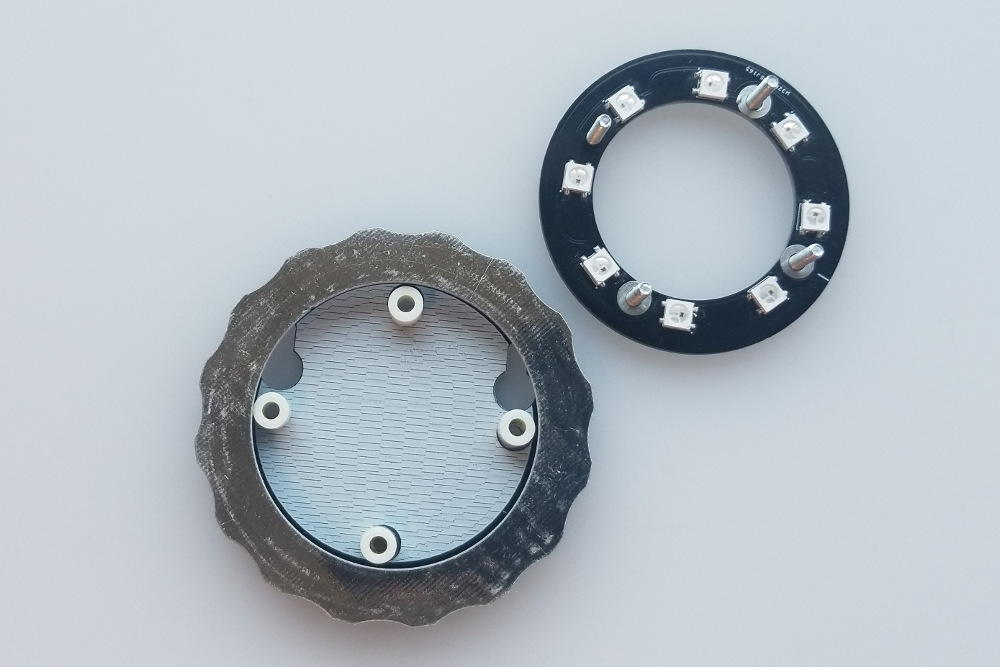
Now pick up your LED retainer board and carefully place it on top, threading each bolt through its corresponding standoff. Three out of the four mounting holes on the boards have exposed copper pads and are highlighted in green in the image below. To get the orientation right, make sure to align the mounting holes relative to the one without the plated through holes (highlighted in red) for the base board and LED ring.

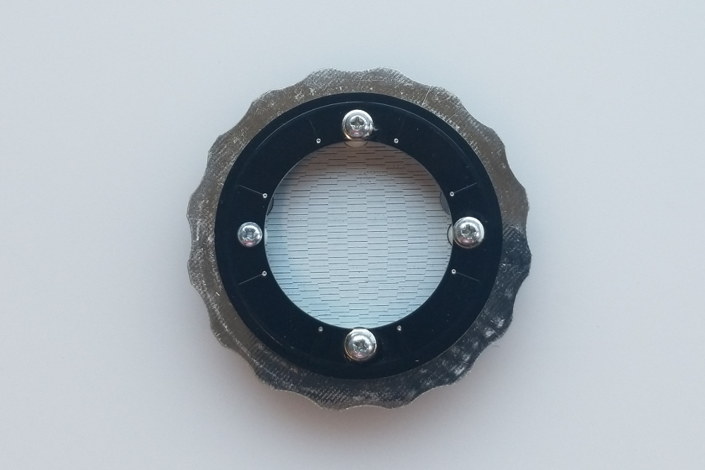
If your orientation isn't right, the LED ring won't work. Carefully lift the entire stack and place the nuts on the end of the bolts.
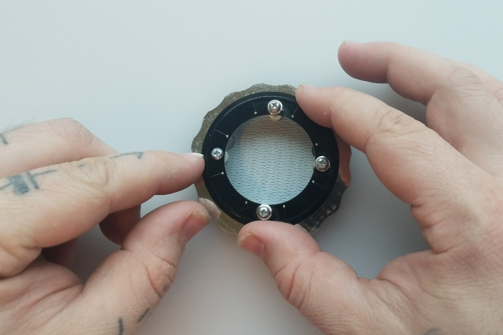
Tighten everything down firmly but not crazy tight.

Step 5 - Enjoy!
You can now solder some wires or pin headers to the 5-pin header on the base board and hook it up to your project!