Experimental Products: SparkX products are rapidly produced to bring you the most cutting edge technology as it becomes available. These products are tested but come with no guarantees. Live technical support is not available for SparkX products.
The Rotary Dial Kit is designed to be a simple interface device for your project. Input is achieved using a rotating encoder bezel and output is handled by a ring of addressable RGB LEDs along the inside edge of the ring. Two keyhole hangers are milled into the back of the Rotary Dial so it can be wall mounted.
The design was inspired by the rotating bezel on my Samsung Gear smartwatch as well as wall-mounted IoT devices such as the Nest thermostat.
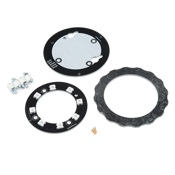
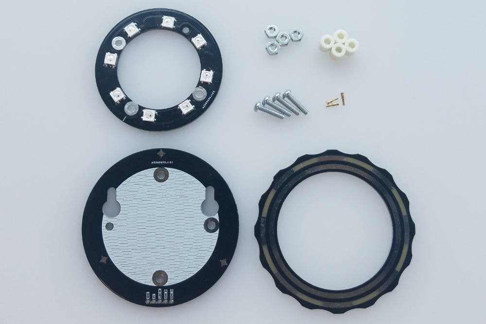
To assemble the kit, you'll need:
Make sure you have everything that you need. The kit includes three PCBs, three pogo pins, four 4-40 bolts, four 4-40 nuts and four 1/4" standoffs.
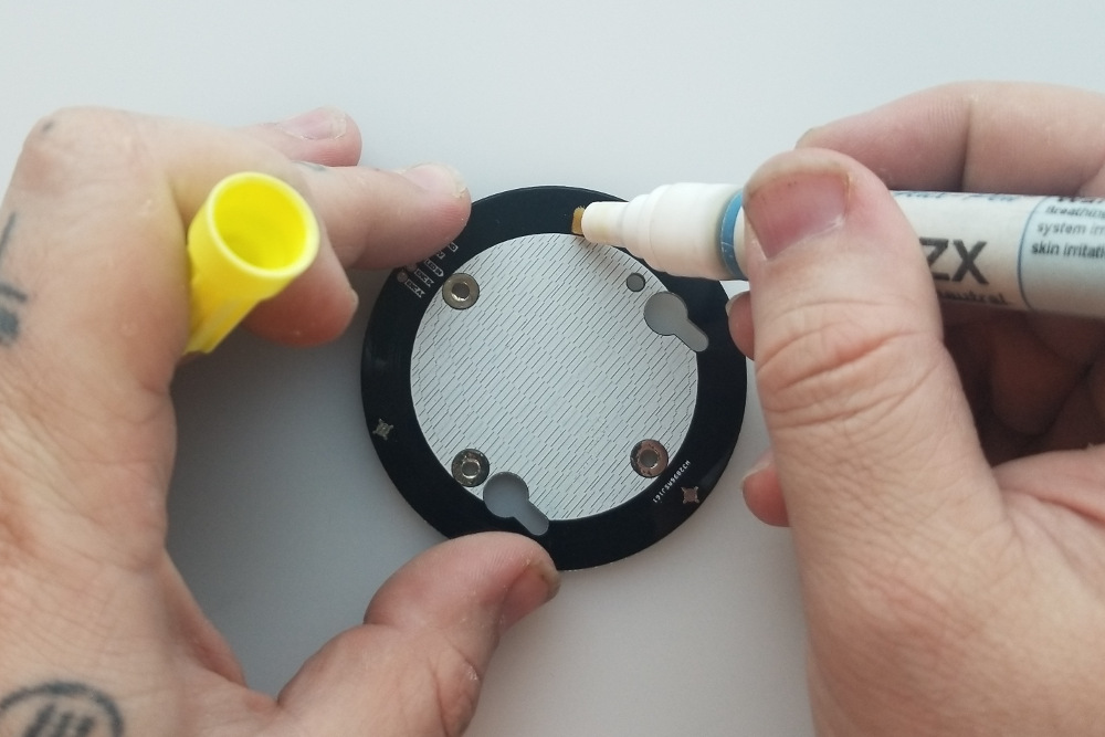
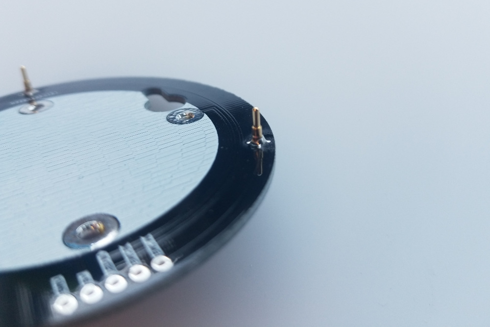
The trickiest part of the assembly will be soldering these pins. It's not too tough, though, so let's get it out of the way now! Start off by applying some flux to each pad, if you have it.
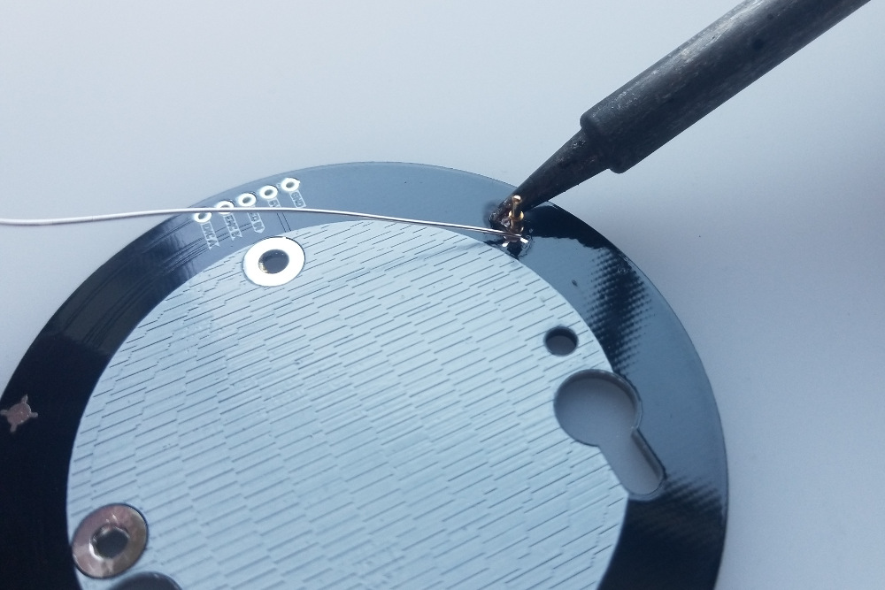
Then place a pogo pin on it's pad and center it as best you can. Don't worry too much about it because it will self-center if you add enough solder. Very carefully apply solder to the pad and allow it to flow to the pin. Add enough solder so that there is a rounded pool around the base of the pin. Once you have a small blob of solder, pull the iron away swiftly and smoothly, careful not to knock over the pogo pin. The surface tension of the still-molten solder should drag the pogo pin to the center of the pad.
Check to make sure that the pin is aligned vertically. It doesn't need to be perfectly perpendicular to the board, but it should be sticking relatively straight up. You may need to grab the pin with some tweezers, reheat the solder, and press it down onto the pad to get it aligned.
Repeat this process for each pin.
The bolts that hold the assembly together are also the signal route for the RGB LEDs on the retainer ring, so it's important to create a good electrical connection. To aid in this, add a little bit of solder to the face of each standoff hole on the back of the base board and the front of the retainer board. Make sure not to overdo it and make the hole too tight for the bolt to go through. The goal is to make a little bump for the nut or the head of the bolt to tighten against.

Now it's time to stack everything together! There are probably a lot of ways to accomplish this, but this is the way I find easiest.
Start by putting the 4-40 bolts through the front of the retainer ring (the board with the LEDs on it) so that the LEDs are on the opposite side from the head of the bolts. Now set this aside and place your base board with the pogo pins facing up.
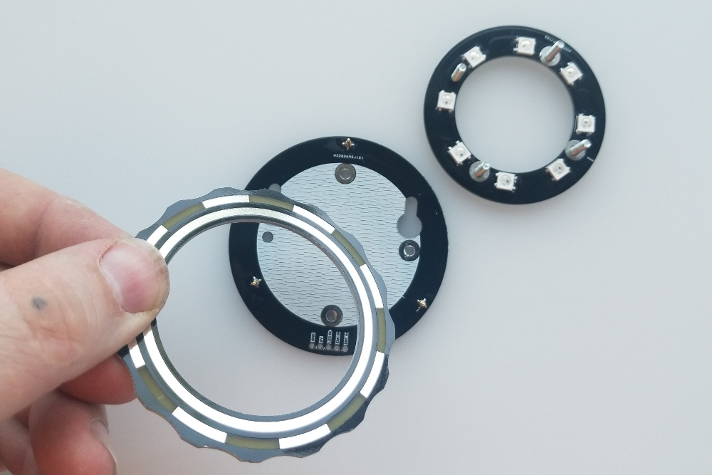
Carefully place a nylon standoff over each of the four standoff holes and place the ring pcb with the shiny side facing up and the tracks facing down onto the pogo pins.
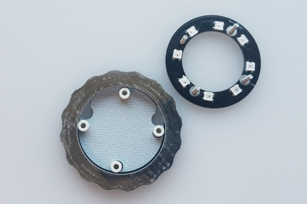
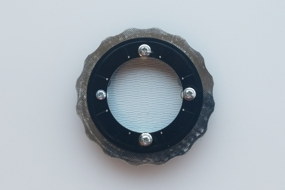
Now pick up your LED retainer board and carefully place it on top, threading each bolt through its corresponding standoff. Three out of the four mounting holes on the boards have exposed copper pads and are highlighted in green in the image below. To get the orientation right, make sure to align the mounting holes relative to the one without the plated through holes (highlighted in red) for the base board and LED ring.

If your orientation isn't right, the LED ring won't work. Carefully lift the entire stack and place the nuts on the end of the bolts.
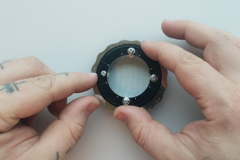
Tighten everything down firmly but not crazy tight.

You can now solder some wires or pin headers to the 5-pin header on the base board and hook it up to your project!
Note: This example assumes you are using the latest version of the Arduino IDE on your desktop. If this is your first time using Arduino, please review our tutorial on installing the Arduino IDE. If you have not previously installed an Arduino library, please check out our installation guide.
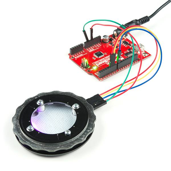
Here are two simple Arduino examples to get you started. Both of them have been tested to work with the SparkFun RedBoard with the following connections:
| RedBoard | Rotary Dial |
|---|---|
| GND | GND |
| 5V | 5V |
| D8 | LED IN |
| D5 | ENC A |
| D6 | ENC B |
Once connected, your setup should look similar to the image below.
Both examples also make use of the PJRC Encoder Library and the Adafruit NeoPixel Library.
This example uses pieces of the NeoPixel example code combined with pieces of the Encoder example code to implement a color selector. As you turn the encoder wheel one direction or the other, you will cycle through the RGB color space on all eight RGB LEDs at once.
language:c
#include <Adafruit_NeoPixel.h>
#include <Encoder.h>

Encoder myEnc(5, 6);

Adafruit_NeoPixel strip = Adafruit_NeoPixel(8, 8, NEO_GRB + NEO_KHZ800);

void setup() {
  strip.begin();
  strip.show();
}

long oldPosition  = -999;

void loop() {
  long newPosition = myEnc.read();
  if (newPosition != oldPosition) {
    oldPosition = newPosition;

    for(int i = 0 ; i < 8; i++){
      strip.setPixelColor(i, Wheel((newPosition*5) & 255));
    }

    strip.show();

  }

}

// Input a value 0 to 255 to get a color value.
// The colours are a transition r - g - b - back to r.
uint32_t Wheel(byte WheelPos) {
  WheelPos = 255 - WheelPos;
  if(WheelPos < 85) {
    return strip.Color(255 - WheelPos * 3, 0, WheelPos * 3);
  }
  if(WheelPos < 170) {
    WheelPos -= 85;
    return strip.Color(0, WheelPos * 3, 255 - WheelPos * 3);
  }
  WheelPos -= 170;
  return strip.Color(WheelPos * 3, 255 - WheelPos * 3, 0);
}
This example is almost identical except that as you turn the encoder ring, only one LED will light at a time, moving in the same direction that you turn the ring.
language:c
#include <Adafruit_NeoPixel.h>
#include <Encoder.h>

Encoder myEnc(5, 6);

Adafruit_NeoPixel strip = Adafruit_NeoPixel(8, 8, NEO_GRB + NEO_KHZ800);

void setup() {
  strip.begin();
  strip.show();
}

long oldPosition  = -999;

void loop() {
  long newPosition = myEnc.read();
  if (newPosition != oldPosition) {
    oldPosition = newPosition;

    for(int i = 0 ; i < 8; i++){
      strip.setPixelColor(i, 0);
    }

    int dot = abs(newPosition)%8;
    strip.setPixelColor(dot, Wheel((newPosition*5) & 255));
    strip.show();

  }

}

// Input a value 0 to 255 to get a color value.
// The colours are a transition r - g - b - back to r.
uint32_t Wheel(byte WheelPos) {
  WheelPos = 255 - WheelPos;
  if(WheelPos < 85) {
    return strip.Color(255 - WheelPos * 3, 0, WheelPos * 3);
  }
  if(WheelPos < 170) {
    WheelPos -= 85;
    return strip.Color(0, WheelPos * 3, 255 - WheelPos * 3);
  }
  WheelPos -= 170;
  return strip.Color(WheelPos * 3, 255 - WheelPos * 3, 0);
}

Now that you've successfully got your Rotary Dial up and running, it's time to incorporate it into your own project!
For more information, check out the resources below:
Need some inspiration for your next project? Check out some of these related tutorials:
learn.sparkfun.com | CC BY-SA 3.0 | SparkFun Electronics | Niwot, Colorado