RETIRED - Pi Wedge B+ Hookup Guide
This Tutorial is Retired!
The SparkFun Pi Wedge B+ kit has been retired. If you are still looking for a way to connect to the Raspberry Pi's 40-pin header, there is a preassembled 40-pin Pi Wedge version available.
View the updated tutorial: Preassembled 40-pin Pi Wedge Hookup Guide
 Byron J.
Pin Mapping
Changes With the B+
The Raspberry Pi foundation introduced a number of changes with the B+. The changes include
- 40 pin GPIO connector in place of the B's 26 pin connector. It adds
- Nine more GPIO pins
- ID_SC and ID_SD pins to identify external peripherals
- Regulated audio power supply
- 4 USB ports
- Micro SD slot, replacing the full-size SD slot on the B.
An Extra I2C bus?
As part of the B+ improvemets, the Raspberry Pi Foundation has standardized the specification for add-on boards, in what they call the "Hardware Added On Top" (HAT) specification. It standardizes the physical form factor for add-on boards, and includes a provision for the B+ to automatically identify and initialize HATs at startup. It uses an I2C bus to read a description from an EEPROM on the HAT, similar to cape identification on the Beagle Bone Black.
This I2C bus is implemented with the ID_SC and ID_SD pins (pins 27 and 28 of thev 40-pin connector) - but before you get too excited about adding peripherals on that bus, observe the note in the schematic for that port.
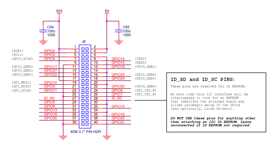
This is further clarified in the HAT design guide
On a Model B+, GPIO0 (ID_SD) and GPIO1 (ID_SC) will be switched to ALT0 (I2C-0) mode and probed for an EEPROM. These pins will revert to inputs once the probe sequence has completed.
The only allowed connections to the ID_ pins are an ID EEPROM plus 3.9K pull up resistors. Do not connect anything else to these pins!
So if you want I2C on the B+, you'll need to use I2C-1, on pins 3 and 5 of the 40-pin connector, marked SDA and SCL on the Pi Wedge B+.
The HAT specifications and other information are hosted on GitHub. If you're designing a HAT, you'll want to start by reading the HAT Design Guide, and possibly perusing the B+ addons forum.
Signal Location
The Pi Wedge reorganizes the I/O pins on the Pi, putting similar functions on adjacent pins. The SPI, I2C and UART signals are all grouped near each other.
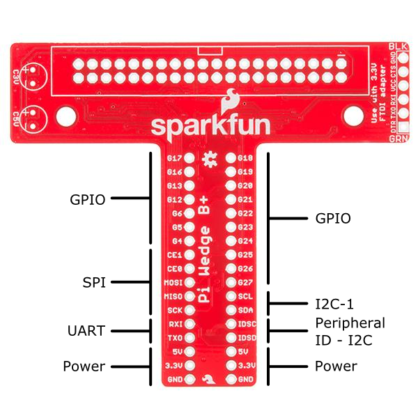
The pins are labeled, though the labels are short to fit the space available on the PCB. The UART, SPI and I2C pins are marked with their communication bus functions, but they can also available as GPIO pins when configured in that mode.
The following table denotes the assignment of signals on the Pi Wedge, including the peripheral and alternate GPIO assignments where appropriate.
| Function | GPIO# | Function | GPIO# | |
| GPIO 17 | GPIO18 | |||
| GPIO 16 | GPIO19 | |||
| GPIO 13 | GPIO 20 | |||
| GPIO 12 | GPIO 21 | |||
| GPIO 6 | GPIO 22 | |||
| GPIO 5 | GPIO 23 | |||
| GPIO 4 | GPIO 24 | |||
| SPI CE 1 | GPIO 7 | GPIO 25 | ||
| SPI CE 0 | GPIO 8 | GPIO 26 | ||
| SPI MOSI | GPIO 10 | GPIO 27 | ||
| SPI MISO | GPIO 9 | SCL | GPIO 3 | |
| SPI CLK | GPIO 11 | SDA | GPIO 2 | |
| UART RXI | GPIO 15 | ID SC | GPIO 0 | |
| UART TXI | GPIO 14 | ID SD | GPIO 1 | |
| 5V | 5V | |||
| 3.3V | 3.3V | |||
| GROUND | GROUND |