RedBot Sensor - Wheel Encoder
This Tutorial is Retired!
This tutorial covers concepts or technologies that are no longer current. It's still here for you to read and enjoy, but may not be as useful as our newest tutorials.
 HelloTechie,
  SFUptownMaker
Introduction
RedBot Wheel Encoder
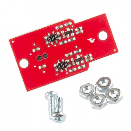
The Wheel Encoder board uses the same sort of infrared reflection sensors as the line sensors to watch a notched wheel attached to the axle spin. By counting the number of falling edges the sensor detects, you can determine how far the robot has traveled.
There should be 16 falling edges per full rotation of the wheel, and, since the wheel is about 2.5 inches (65mm) in diameter, that corresponds to about 8 inches or 200mm traveled per full revolution. Now, to forestall angry messages about conversions and precision of measurement (for instance, if you ask Google how many mm are in 2.5 inches, it'll tell you 63.5, not 65, and the circumference of a 2.5in diameter is certainly not exactly 8 inches), I invite you to consider this your first lesson in precision and tolerance. Given all the tolerances involved in this system, 8 inches/200mm per revolution is almost certainly a "good enough" answer, and if you need better than that, you'll need a more expensive robotics platform.
Assembly
We will be placing screws that will later hold the RedBot Sensor - Wheel Encoder to the bottom chassis.
Locate the following:
- 1x Bottom Chassis Piece
- 2x 4-40 3/8" Phillips Screws
- 2x 4-40 Hex Nuts
Locate the two positions on the bottom chassis piece where the 4-40 screws will go. In this step, it doesn't matter what side you use, since both sides of the chassis are indential.
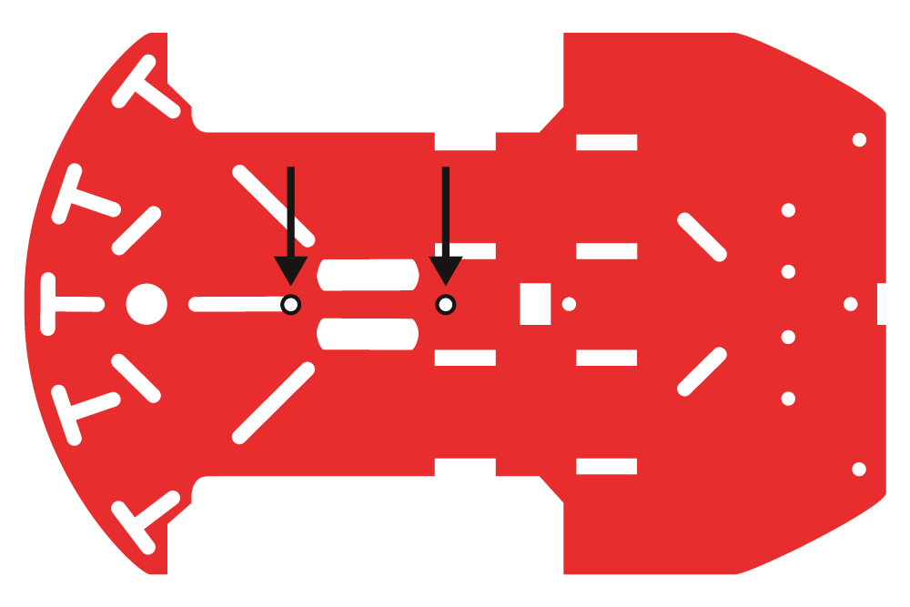
Place one of the 4-40 screw through the chassis piece in the correct location. This side of the chassis piece will now be your bottom side.

Tightly screw down the 4-40 hex nut on the top side of the chassis piece to hold the 4-40 screw down.
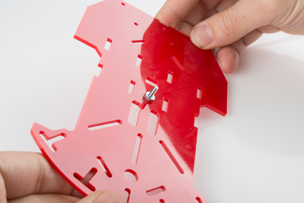
Place the second 4-40 screw and nut in the second located position on the chassis piece. You will want to place the 4-40 screw through the bottom side of the chassis. Then screw in the 4-40 nut on the top side of the chassis.

Adding RedBot Wheel Encoder
Locate the following:
- 1x RedBot Sensor - Wheel Encoder
- 2x 4-40 Hex Nuts
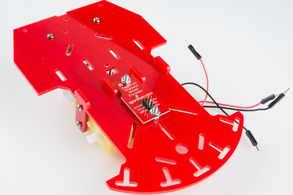
With the six pin male header side on the RedBot Sensor - Wheel Encoder facing upwards, place down the encoder on the top side of the bottom chassis piece where the 4-40 screw are. Pay close attention that the six pin male header side is also closest to the front side of the chassis. Using two 4-40 hex nuts, tighten down the RedBot Sensor - Wheel Encoder on the top side of the bottom chassis piece.
Connecting the Wheel Encoder the the RedBot Mainboard
Add four jumper wires to the RedBot Sensor - Wheel Encoder. There should be a jumper wire each one of the following pins: OUTB, OUTA, VCC, and GND. You can then connect the jumper wires to the following pins on the RedBot Mainboard.
SparkFun RedBot Sensor - Wheel Encoder → RedBot Mainboard
- OUTB → A2
- OUTA → 3
- VCC → 5V
- GND → GND
Code Example
To help you make getting your robot moving as easy as possible, we've written an Arduino Library, which can be downloaded here. Here's a walk-through of the commands that the library provides. If you need a refresher on how to install an Arduino library, please see our library tutorial.
The Arduino library linked above includes example code.
Wheel Encoder
The Encoder board is supported by the library to allow the program to tally encoder ticks in the background, without requiring the user's attention. Of course, the user must still check the count periodically to determine whether or not some action is required, but this requires less processor overhead than constantly monitoring for a pin state change.
RedBotEncoder(int lPin, int rPin);
The class constructor accepts two parameters: the pin numbers to be assigned to the left and right wheels. Most of the pins on the RedBot board may be used for this purpose; pins A6 and A7 cannot be, however, as they are analog-only inputs and this signal is inherently digital.
void clearEnc(WHEEL wheel);
clearEnc() clears the odometer of a given wheel. It accepts as a parameter either LEFT, RIGHT, or BOTH, with the obvious meaning.
long getTicks(WHEEL wheel);
getTicks() returns the number of counts currently recorded for the given wheel. Note that, unlike for clearEnc(), BOTH is not a valid input, since only one value can be returned at a time.
Resources and Going Further
Get moving!
Hopefully, this guide has given you enough information to get started with the SparkFun RedBot Sensor - Wheel Encoder.
We have a new assembly guide that goes over how to assemble the rest of the RedBot that can be found here:
- RedBot Assembly Guide Rev 02 Please note: This guide has the hardware in this version of the RedBot kit. It showcases the Dagu Wheel Encoder instead of the RedBot Sensor - Wheel Encoder.
- RedBot Assembly Guide Please note: This guide has the hardware in an retired version of the RedBot kit. It showcases the RedBot Sensor - Wheel Encoder, but not the newest hardware.
Look for more sensors, kits and content around the RedBot platform!
Once you've mastered the art of line following robots, try you hand at other types of robots.
- You could use a robotic claw and a pan/tilt bracket to design a robot with an arm to fetch items for you.
- Learn more about the MMA8452Q accelerometer in the MMA8452Q Accelerometer Hookup Guide.
- You could create your own remote control using various SparkFun parts.
- And, you can always give your robot a new look with different types of robot chassis.
- Also, check out our HUB-ee Buggy tutorial for more robot ideas.