RED-V RedBoard Hookup Guide
 Englandsaurus,
  bboyho
Hardware Overview
Power & Programming
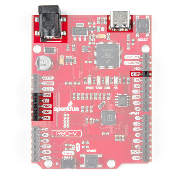
There are a few different ways to power the SparkFun RED-V RedBoard:
- USB-C
- barrel jack connector
- power pins broken out on the edge of the board
The easiest way (which will also allow you to program your board) is to simply plug it into your computer via USB-C. This will provide 5V to the board and will also allow you access to the super cool USB-to-JTAG interface for programming. Once you've programmed your RED-V however, you may want to have it running off of a different power supply. If you use a wall wart on the USB-C connector, make sure it outputs a regulated 5V DC. You can also use the black barrel jack, in which case you'll need any wall adapter between 7 & 15 Volts DC. Or you can also power the board through the header pins broken out on the edge of the board. If you are using VIN and GND, follow the same practice as using a wall adapter and stick to between 7 & 15 Volts. If you are using 5V and GND or 3v3 and GND, make sure that your voltage is regulated when applying power to the 5V or 3.3V pins, respectively.
Always-On Core
The FE310 contains an Always-On (AON) block that allows easy power control of the FE310. It includes its own real-time clock and is also attached to the WAKE button on the board. This allows you to put the FE310 to sleep and wake it up upon a time-generated or user-generated interrupt.

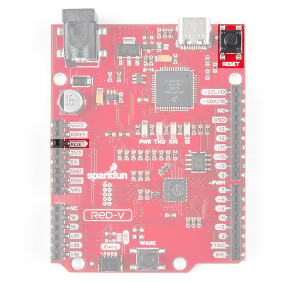
Buttons
The RED-V has two buttons: a RESET button and a WAKE button. The RESET button is pretty self explanatory and is used to reset the FE310. A single tap of the RESET button will run the code loaded onto the FE310's QSPI flash. A quick double tap will put the FE310 into safe bootloader mode, which will allow you to flash new code to the RED-V if you've managed to really mess things up (i.e. Oops I put the core to sleep and forgot to add a way to wake it up). The pin is also broken out on the edge of the board. Adding a jumper wire from this pin to GND will reset the board as well.
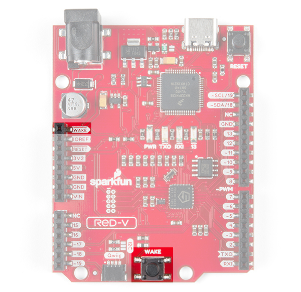
The RED-V is also equipped with an Always-On or AON core (mentioned above) which can be programmed to shut down the main core of the FE310 and wake it up upon a button-generated or user-generated interrupt. The WAKE button can be configured in software to wake the FE310 from deep sleep. This button is also broken out to the header pin nearest the barrel jack if you'd like to use an external source to wake the FE310. Adding a jumper wire from this pin to GND will wake the board as well.
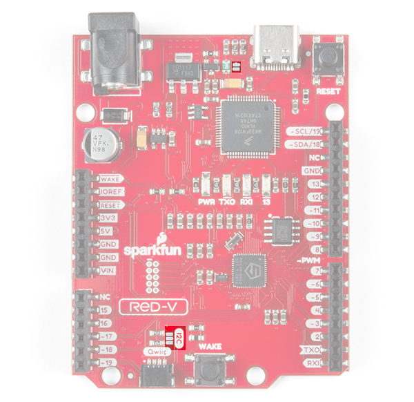
Jumpers
The FE310 has a few jumpers as well, all of which are open by default. The two jumpers located next to the I2C label is for the I2C pull-up resistors. These resistors are not attached by default as there are I2C pull-up resistors on all SparkFun Qwiic slaves. If you're using a 3rd party board, you may need to close these jumper by the Qwiic connector to attach the pull-ups to the I2C bus. The jumper by the USB-C connector is for bypassing the 0.5A PTC fuse. This is for special cases where you need a lot current. Most of the time, you can leave this jumper open.
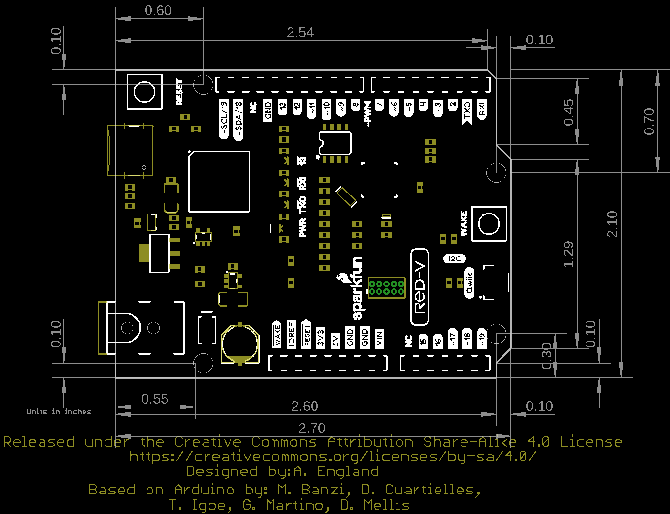
Dimensions
The RED-V RedBoard uses the Arduino Uno footprint. There are four mounting holes on the board.