Red Hat Instrument Kit Hookup Guide
Part 2: Breadboarding, 555 timer, and potentiometer
What is a circuit? A circuit is a closed loop that electricity can travel around. At its most basic, a circuit consists of three parts:
- A voltage source: The power for the circuit
- A load: The thing that is being powered, like a motor, buzzer, or light
- The circuit path: The continuous path that the current follows as it travels around the circuit
An example of a simple circuit would be a power source (like a battery), a load (like an LED), and the circuit path (the wires that connect them).
The power/voltage source
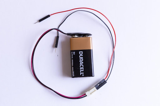
Your kit comes with a 9V battery and 9V snap connector to be used as a power/voltage source. You'll notice that the snap connector has a plastic connector ― the small, white, rectangular box at the end of the red and black wires. This makes it easy to connect to many types of electronics; however, we won’t be using it for our project today. We’ll actually connect the power to the breadboard with jumper wires. The jumper wires in your kit have small metal pins on either side.
The colors of the jumper wires don’t correspond to anything in your kit. Use any two colors that you prefer. That said, make sure you keep track of which jumper is positive and which jumper is negative. By convention, the red jumpers are positive, and the black jumpers are negative/ground.
There are two holes in the plastic molding at the end of the wires coming from the battery pack. Insert a jumper wire into each of these holes like so:
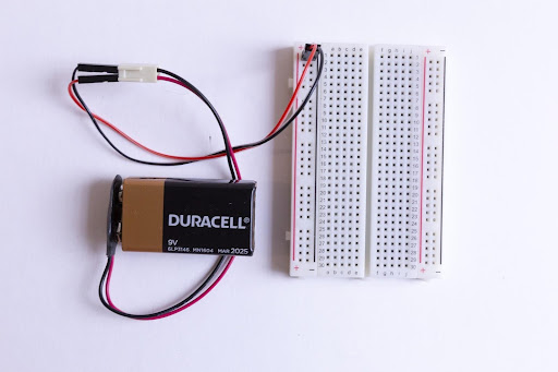
Now insert the other ends into the (+) power rail and the (-) power rail - again making sure that your positive jumper goes to the (+) side of the power rail and the negative jumper goes to the (-) side of the power rail:
The load
For this circuit, we will use a 555 circuit attached to a speaker triggered by a potentiometer. Potentiometers can take multiple shapes. Sometimes, we might see them as knobs that we turn, like volume knobs on radios. Other times, they look like faders that slide up and down; think of some dimmable light switches. They can give us control over things like speed, voltage, or frequency in our circuit kits. As we make adjustments to our knob or fader, we are changing the amount of resistance that a circuit is passing.
For our circuit, we’ll draw our potentiometer using conductive paint or ink. Since we know that circuits are continuous devices, we’ll have to make sure that, whatever instrument we draw, all the lines connect somehow. The ink we used to draw our line above will serve as our potentiometer.
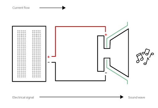
Our circuit culminates in the speaker. If you’ve used headphones or earbuds, or watched TV, you have a pretty good idea what speakers are capable of. For our purposes, the speaker converts the electrical audio signal (in the form of sound waves) from our 555 timer into sound. This is the same basic principle that a guitar amplifier or movie theater sound system uses.
The circuit path
For a circuit to work, the path of the power can’t be interrupted — every piece must connect with another piece. Luckily, we have a breadboard, which is a helpful tool we can use to quickly plug in items and keep them connected. It also lets us create, fix small mistakes, and practice with our components.
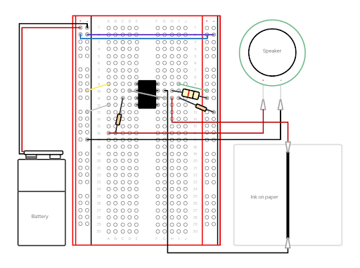
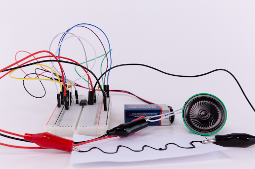
We are going to replicate this circuit (the steps are below). We’re using quite a few jumper wires, so be extra careful to place them into the appropriate coordinate points on your breadboard. We’ll save the special alligator clip connections for last. We’ll use both sides of our breadboard, so remember that each side has a positive (+) and negative (-) power rail, as well as its own unique set of column connections. The left hand columns are labeled A-E, and the right hand columns are F-J.
Create your circuit:
- Place the 555 timer circuit so that one set of pins aligns with E9-E12 and the other set aligns with F9-F12. This will mean that the 555 timer bridges the center trench/gap. Gently press into place.
- Connect a jumper wire from positive power (+) rail 2 on the left side to positive power (+) rail 2 on the right side
- Connect a jumper wire from negative power (-) rail 2 on the left side to the negative power (-) rail 2 on the right side
- On the left side, connect a jumper wire from negative power (-) rail 9 to A9
- On the right side, connect a jumper wire from positive power rail (+) 9 to i9
- Connect a jumper wire from D10 to G11
- On the left side, connect a jumper wire from positive power rail (+) 11 to A12
- On the right side, place the resistor so that it bridges between H10 and positive power rail (+) 10
- On the left side, place a capacitor so that it bridges between C11 and B16
- On the right side, place a capacitor so that it bridges between i11 and the negative power rail (-) 13
Connecting the Alligator Clip Jumper Wires
- On the left side, connect the pin end of an alligator clip jumper wire to A16 and clip the other end to the positive wire (+) of the speaker
- On the left side, connect the pin end of an alligator clip jumper wire to negative power rail (-) 15 and clip the other end to the negative wire (-) of the speaker
- On the right side, connect the pin end of an alligator clip jumper wire to H11 and clip the other end to the ink block on the edge of your drawing paper
- On the right side, connect the pin end of an alligator clip jumper wire to G10
Testing
Once you complete the steps above and place the battery into the pack, you can play the ink like an instrument! To test your build, simply take the loose end of the final alligator clip jumper wire and tap it against any part of the conductive ink/paint line.
Redesign your instrument
Now that you see how the system works, take some time to redesign your instrument any way you want. Just remember that it’s best to have a small block of conductive ink on the edge of your piece of paper to anchor the clip to. After you redesign your instrument, all you have to do is reclip the alligator wire that was previously on the edge of your paper with the straight line to the edge of the paper with the new instrument. Tap away!