Red Hat Co.Lab Robotic hand kit curriculum guide
 Evan_Double_U
 Introduction
In this kit, you’ll find everything you need to understand the basics of a continuous rotation (CR) servo and sensor.
The Red Hat® Robotic Hand kit will help you:
- Discover how breadboards work by experimenting with simple circuits using a CR servo.
- Design and construct a hand that can flex and release.
Before You Start
Before you start assembling your kit, there are some things you can do ahead of time to ensure your project will be successful. The information below will tell you how much time you can expect to spend on each part, what tools and materials you'll need, and what you can do before you start your project.
Recommended Age and Prerequisite Skills
This activity is best suited for ages 12-15. There are no specific skills required to complete the project except for the ability to tie a knot and use scissors. No prior knowledge of circuits is assumed.
Time Requirements
- Part one: creating a “hand”--30 minutes
- Part two: continuous rotation servo & string--45 minutes
Tools and Materials
- The Red Hat Co.Lab Robotic Hand kit
- The box: For making our hand
- Scissors: For modifying the cardboard for the experiment (cutting cardboard)
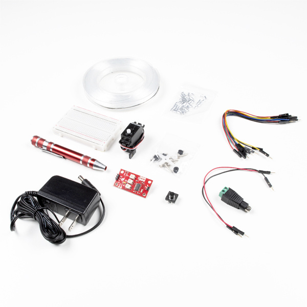
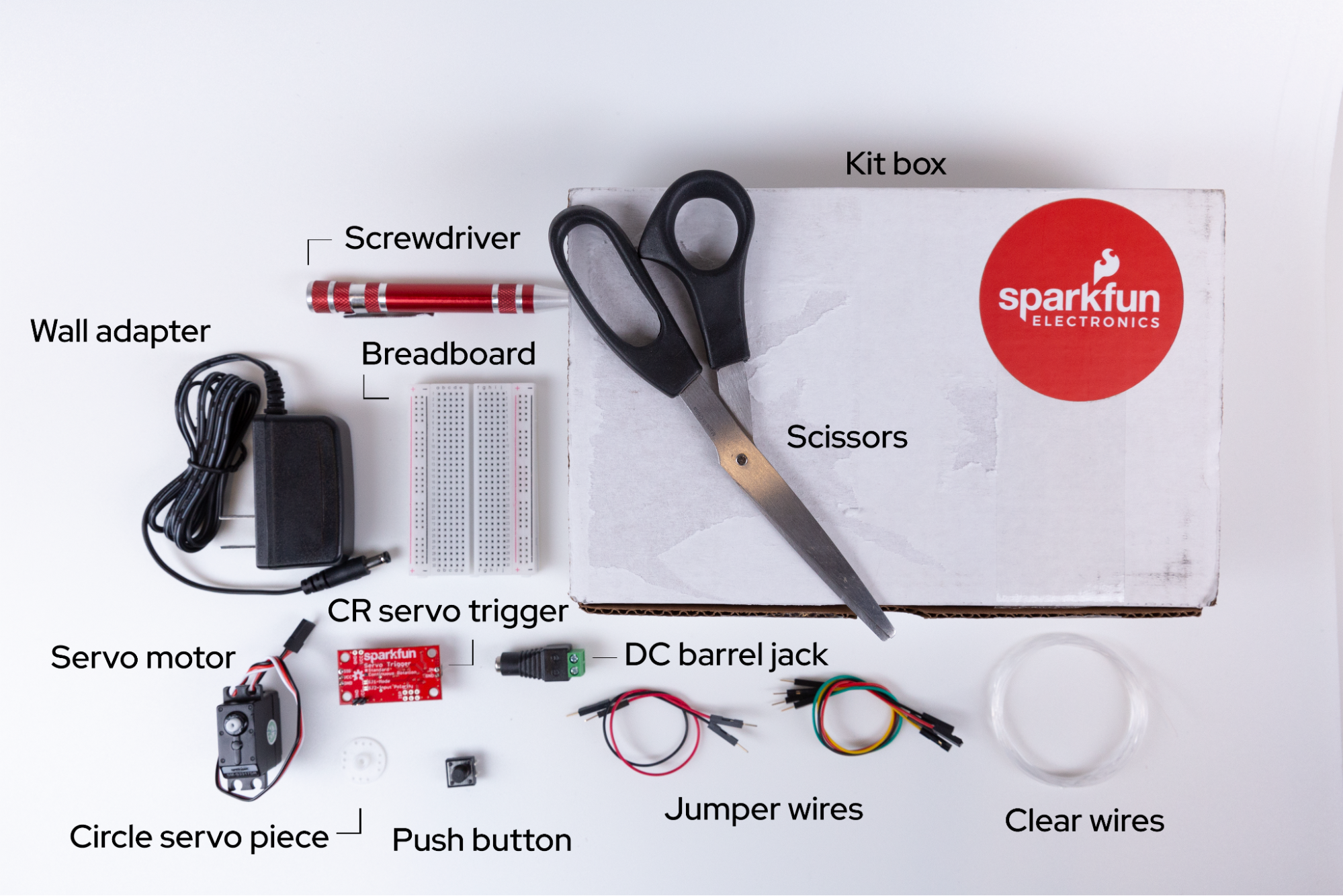
Identify the Parts
It’s helpful to know the parts you’ll use before building. Lay the parts out in front of you on a piece of paper. As you lay them out, pick them up and examine each one. How many pins does it have? What colors are on it? Is each leg of the component the same length? Can you guess what it does on the basis of how it looks or what it's called? Write these observations down next to each part as this will help you organize the pieces as you begin to explore and build.
While you’re laying out the parts for your project, make sure you have the other required materials that didn’t come with your kit (cardboard box and a pair of scissors).
By this point you have:
- Identified each part (and labeled it so it’s easier to find).
- Counted each part to make sure you have the correct number.
- Examined each part to make sure it's not broken.
Now that you’ve completed the setup, you can start to design and experiment.
Resources
Below are in-depth descriptions of the parts in this kit.
- Circuits: The basics of how circuits work, as well as links to more information.
- Breadboards: A thorough examination of the interior mechanics of the breadboard.
- Continuous rotation servo: An explanation of CR servos.
- Servos: A general explanation of servos.
What is a Circuit?
How to Use a Breadboard
Continuous Rotation Servo Trigger Hookup Guide
Part 1: Creating a “Hand”
What does the hand do?
The human hand is a complex machine, made up of skin, bones, muscles, nerves, tendons, and ligaments. Our hands allow us to grip items in many ways and with various levels of power and dexterity. Replicating a hand is very hard to do because of its many components as well as its sense of touch. Imagine the differences between how you lift a pencil to write, how you might lift a heavy bag, and how you open a door. Each of these activities requires different motions, different fingers, and different levels of strength to accomplish the task. As part of the experiment, we’ll focus on how we can replicate the gripping motion of just a few fingers with a circuit and cardboard box.
How can we replicate a hand?
Start by removing some pieces from the cardboard box the kit came in. With the lid open, remove each of the side flaps that would normally tuck into the box when closed.

Next, with the side of the box with the opening facing you (also the side with a half circle cut out near the top), cut a rectangle into the left-hand side. This is where you’ll insert the servo—you can use that part to measure the size of the slot to be created.

On the opposite end of the rectangle, make three fingers by cutting out small gaps. These gaps should resemble very thin rectangles.

Using either a pen or the thinnest end of a screwdriver, poke holes in the center of each finger created. This is best accomplished by opening the lid and flipping it over so that you’re looking at the brown side of the cardboard box. Then, gently apply pressure creating the smallest possible hole in the cardboard.

Next, replicate how fingers typically bend. This means slightly creasing each finger at approximately the same location. These will replicate the second finger knuckle and where the finger connects to the hand. Then, bend the whole lid just below the thin rectangles to replicate how a hand can fold.

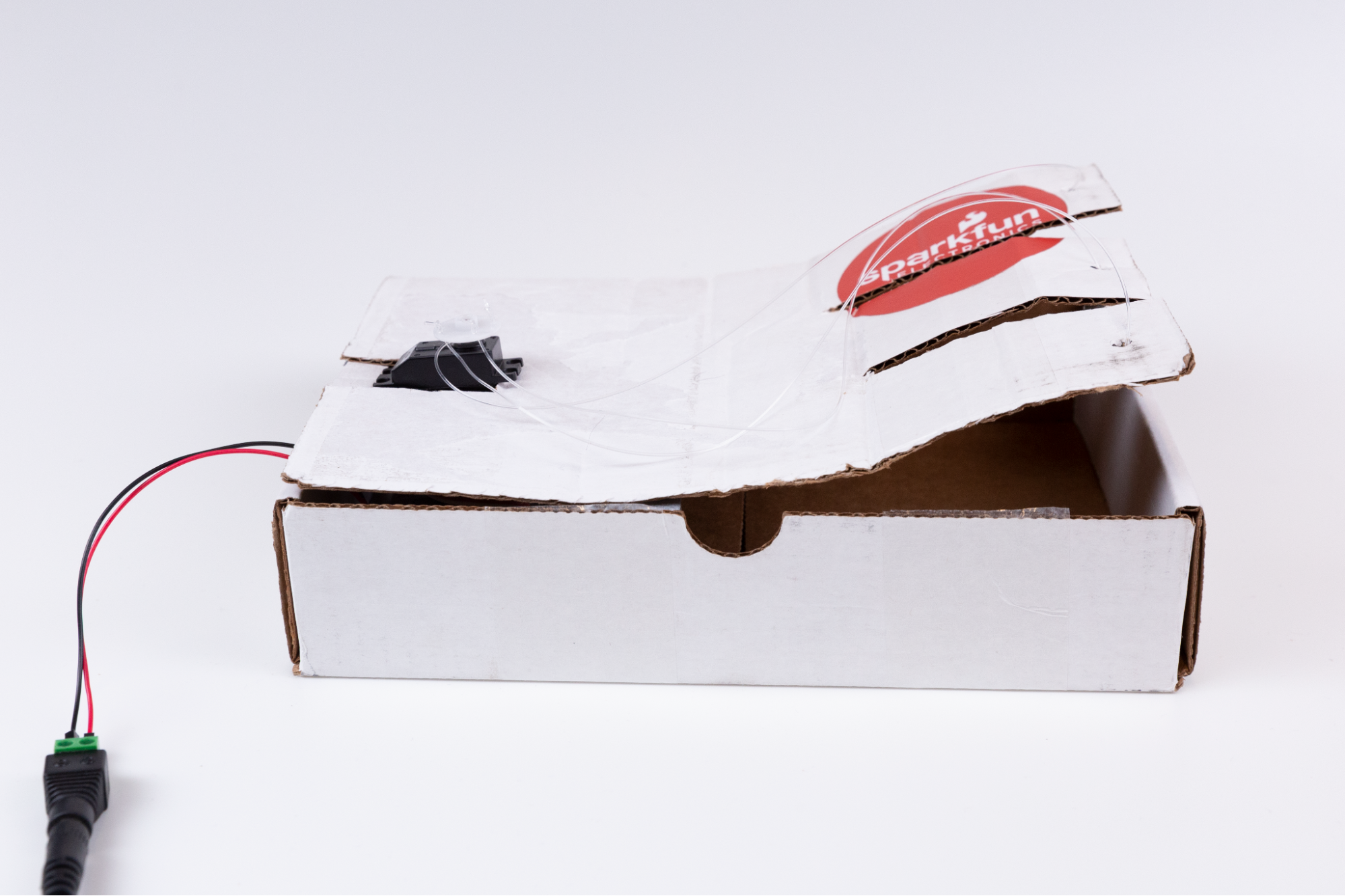
Now you have the beginnings of the hand. Next, measure out three single clear wires. Each one should be about as long as the length of the box plus a half length. To do this, take the clear wire and spool out enough to run the length of the long part of the box and then enough to run back along that same half until you get to the half circle.

For each wire, thread one end through the finger hole you created so that the knot is on the bottom side. Thread the other end upward through the holes in the circle servo piece so that it knots on the top.

Part 2: Breadboarding and the CR Servo
Here's a walkthrough showing the steps of Part 2.
What is a circuit?
A circuit is a closed loop that electricity can travel around. At its most basic, a circuit consists of three parts:
- A voltage source: The power for the circuit.
- A load: The thing that is being powered, like a servo, buzzer, or light. I The circuit path: The continuous path that the current follows as it travels around the circuit.
An example of a simple circuit would be a power source (like a battery), a load (like an LED), and the circuit path (the wires that connect them).
Making the Circuit
1. The power/voltage source
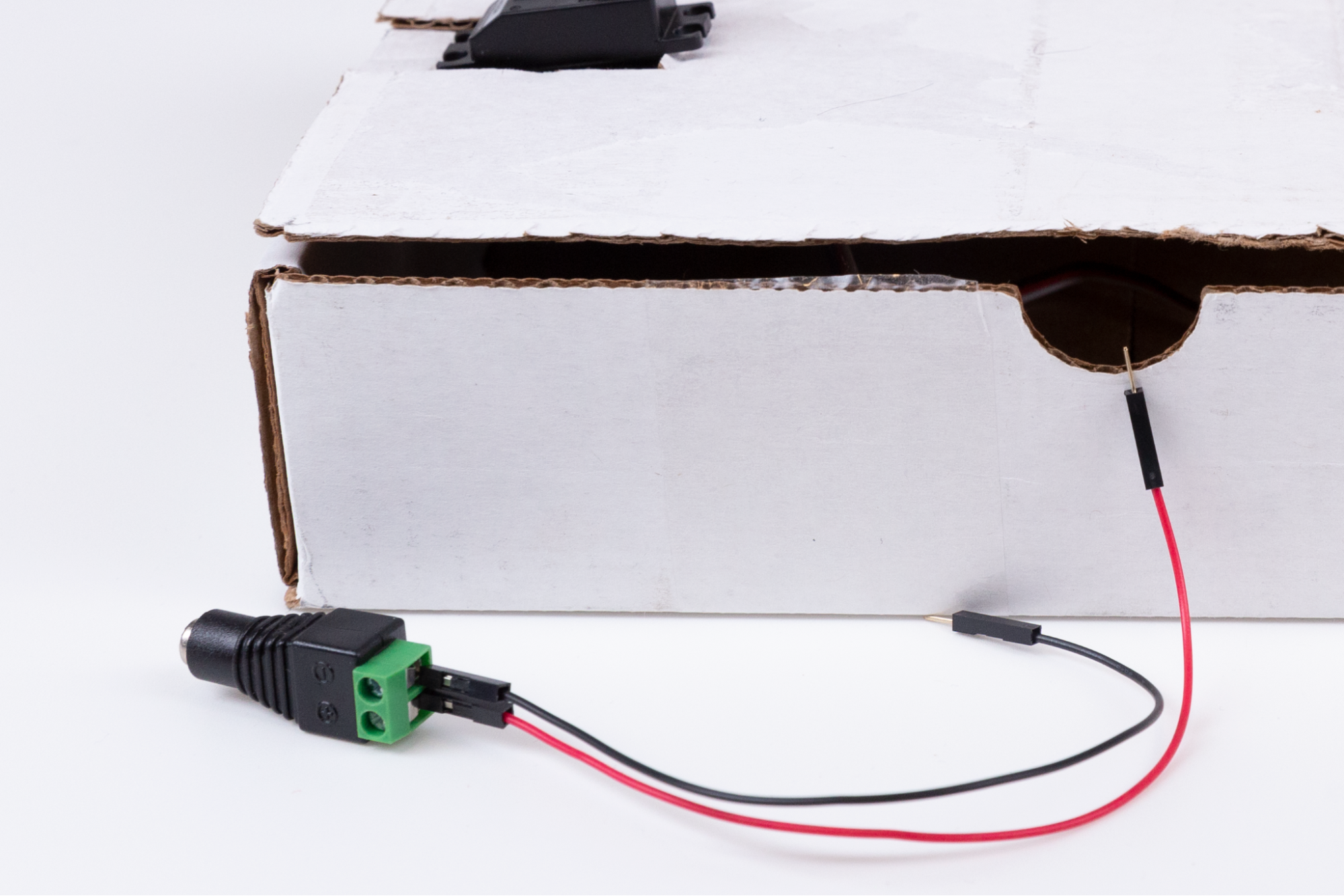
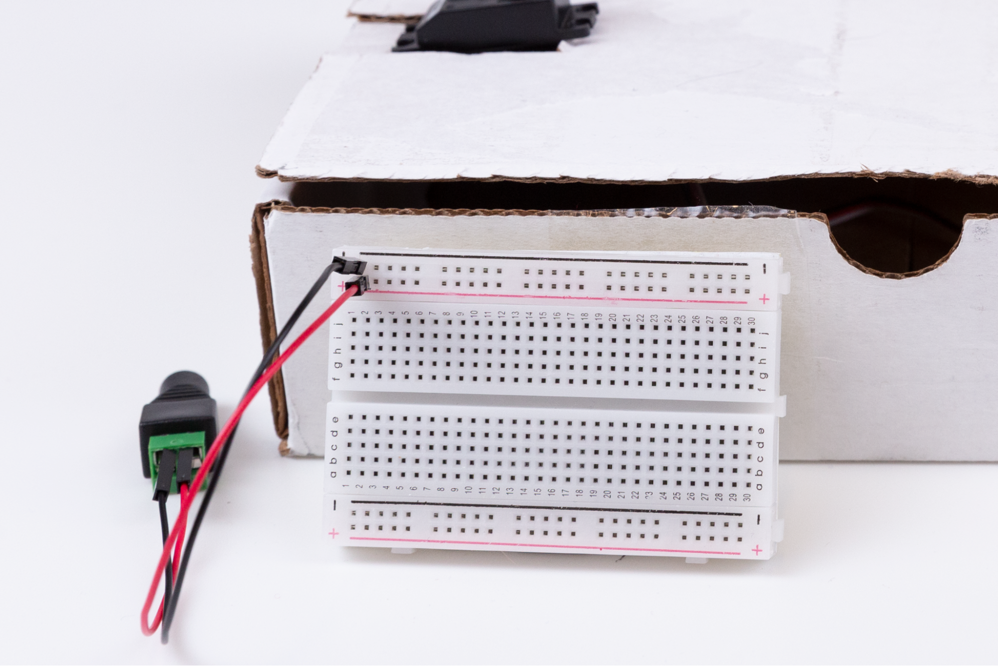
This kit comes with a wall adaptor that connects to the DC barrel jack. Unlike using 9V or AA batteries, this kit requires that we draw power directly from a wall outlet. We won’t plug the adapter into the wall until the last step. In the meantime, prep the barrel jack. The way to connect the barrel jack to the breadboard is with jumper wires, which are short in length and make connecting components quick and easy.
The jumper wires that come in your kit have small metal pins on either side. The colors of the jumper wires don’t correspond to anything in your kit. However, it is convention to use red cables for positive connectors (+) and black for negative connectors (-). The black plastic on the barrel connector is marked with a (+) and (-) sign to indicate positive and negative. Slide one side of the jumper wire into the positive (+) green barrel jack connector and match it to the corresponding positive (+) spot on the right side of the breadboard. Repeat this for the negative (-) connection.
2. The Load
For this step, use a CR circuit attached to a servo triggered by a push button. Pause and take a look at what each of these parts actually does.
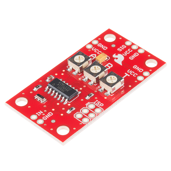
The CR servo trigger is a small robotics board that simplifies the control of servo motors. When an external switch or signal changes state, the servo trigger is able to tell an attached servo to move from position A to position B. To use the servo trigger, connect a hobby servo and a switch, then use the on-board potentiometers to adjust the start/stop positions and the transition time. In this way, you can use a hobby servo in your projects without having to do any programming. It’s important to note that the CR servo trigger has three sets of pins that are attached to it. One set of three pins will be used to connect to the actual servo motor. One set of two pins will be used for connecting jumper wires to the button. This will start and stop the operation of the servo. The last set of two pins, pointing in the opposite direction as the other sets, will be used to directly insert the servo trigger into the breadboard power rails. Make sure you note these different pin configurations before following the instructions later in this guide.
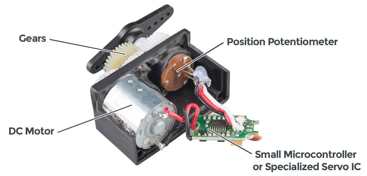
A servomechanism can refer to many different machines that have been around for a while. Servos are found in everything from heavy machinery, to power steering in vehicles, to robotics, and a wide variety of electronics. If you open up a standard hobby servo motor, you’ll usually find three core components, a DC motor, a controller circuit, and a potentiometer or similar feedback mechanism. The DC motor is attached to a gearbox and output/drive shaft to increase the speed and torque of the motor. The DC motor drives the output shaft. The controller circuit interprets signals sent by the controller, and the potentiometer acts as the feedback for the controller circuit to monitor the position of the output shaft. Nearly all hobby servos have a standard three-pin connector to power and control the servo. With a servo, you can power and control the direction, speed, and position of the output shaft with only three wires.
A switch is a component that controls the openness or closedness of an electric circuit. It allows control over current flow in a circuit (without having to actually get in there and manually cut or splice the wires). Switches are critical components in any circuit that requires user interaction or control. A switch can only exist in one of two states: open or closed. In the off state, a switch looks like an open gap in the circuit. This, in effect, looks like an open circuit, preventing current from flowing. In the on state, a switch acts like a piece of conducting wire. This closes the circuit, turning the system on and allowing current to flow unimpeded through the rest of the system.
3. The Circuit Path
For a circuit to work, the path of the power can’t be interrupted—all pieces have to be in contact. Luckily, you have a breadboard that’s a helpful tool you can use to quickly plug in items and keep them connected. You can also create, fix small mistakes, and practice with the components.
What is a breadboard?
Start by taking a look at the breadboard that’s included in your kit:
First, notice there are two long columns of holes running down each side of the board, one with a red line beside it, and one with a black line. These are called the power rails, and all the holes in a single power rail are connected to each other. If power is connected to one hole in the column, it's connected to all the other holes in the column.
There are two holes in the plastic molding at the end of the wires coming from the wall plug. Insert a jumper wire into each of these holes and insert the other ends into the (+) power rail and the (-) power rail.
Second, all the holes in a numbered row are connected to each other, but this connection is broken at the small trench or indent that runs down the center of the board. Each side could be its own separate circuit. Our project will jump over the trench using jumper wires and send power back and forth.
You can view a breadboard as a series of columns (labeled A-E and F-J) and rows (labeled 1-30). Remember, the divide in the middle means A5 isn’t connected to F5. When you get to the instructions below, you’ll use this row and column system to mark where connections should be made (A6, E3, H23, etc.).

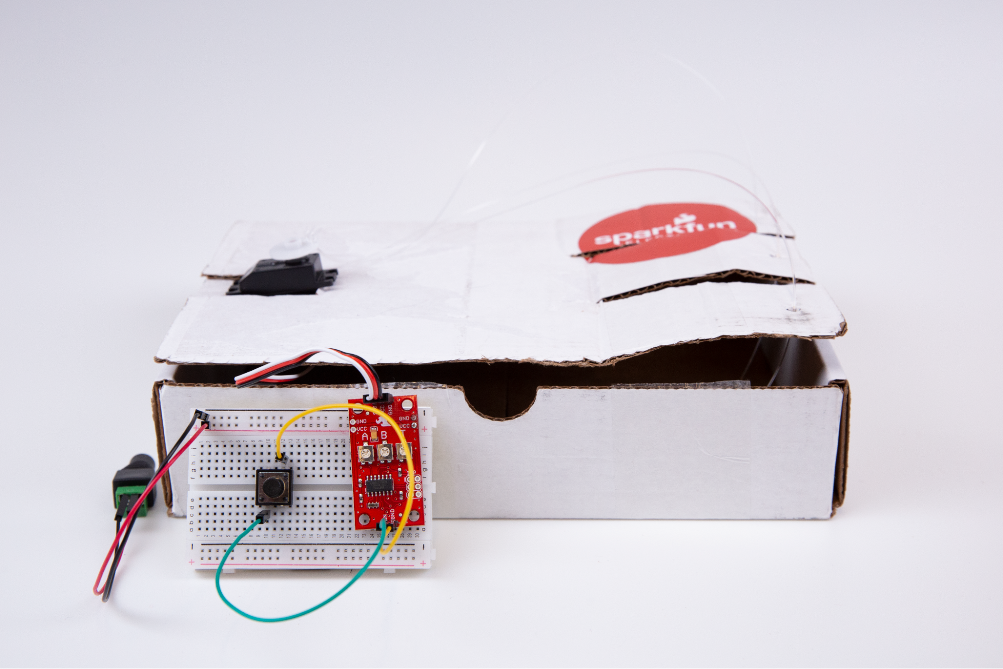
Replicate this circuit show above (the steps are below). You’ll only use a few jumper wires but be especially careful to place them into the appropriate coordinate points on your breadboard. We won’t connect to the power adapter until the last step.
Create your circuit as follows:
- Locate the set of two pins that point in the opposing direction as the other pin connectors. Place the CR servo trigger circuit so that these pins align with the positive (+) and negative (-) power rails on the right side of the breadboard. Gently press into place.
- Connect the button so that the left side is seated into D10 and D12 with the right side seated into G10 and G12.
- Locate the two pins on the servo trigger pointing up. Connect the socket side of a jumper wire to the pin labeled IN and the pin side of the jumper wire to C10.
- Connect the socket side of a second jumper wire to the pin labeled GND and the pin side to H12.
- Connect the black three-pin connector from the servo to the remaining three-pin connectors on the servo trigger so that the black wire is connected to the pin labeled GND.
- Make sure the black and red wires from the barrel jack power supply are connected as discussed in the circuit section above.
Testing
Once you complete the steps above and plug the DC power supply into the wall, you can begin tinkering with your robotic hand. To test your build, simply click the button and watch the servo move. At this point, you’ll want to tinker with the white knobs on the continuous rotation servo trigger. On the circuit board, you will find three potentiometers: "A" sets the position the servo sits in while the switch is open, "B" sets the position the servo moves to when the switch is closed, and "T" sets the time it takes to get from A to B and back.
As you click the button, you’ll find that by twisting the white knob labeled “B” on the servo trigger changes the direction of the servo.
Troubleshooting
Here are some things to look for if your project isn't working (and for some great illustrations and further explanations of these, see "Common mistakes" on the Science Buddies site.)
Check your connections
- Double check the coordinates in the instructions to make sure the pins are completely inserted into the matching holes on the breadboard.
- Make sure components are fully seated in the breadboard. A component should go into the breadboard at least 4-5 mm (or a little less than the thickness of a pencil) when it's fully inserted.
- Check for shorts. When components get connected accidentally, this can cause a short circuit.
- Check the polarity of the capacitors and make sure they match the instructions.
Check your power
- Make sure your batteries are fully inserted.
- Make sure your batteries work.
Full Kit Contents List
If you need to replace a part, here is a list of the individual components that make up the Red Hat Co.Lab Robotic Hand kit.
- 1x Breadboard
- 1x Servo - Continuous Rotation (Micro Size)
- 1x SparkFun Servo Trigger - Continuous Rotation w/ Headers
- 1x Wall Adapter Power Supply - 5VDC, 2A (Barrel Jack)
- 1x DC Barrel Jack Adapter - Female
- 1x Pocket Screwdriver Set
- 1x Jumper Wires M/M 2-Pack
- 1x Jumper Wires M/F 10-Pack
- 1x Momentary Pushbutton
- 1x Strong Clear Nylon Fishing Wire
Resources and Going Further
After you’ve built your robotic hand, check out the Red Hat Open Source Stories film, E-nable. This film shows us how we can design and create for those with differing abilities while growing our empathy for those who experience the world differently.
Want more? Check out additional Red Hat Co.Lab kits at red.ht/colab-kits.