Qwiic Quad Relay Hookup Guide
 Elias The Sparkiest
Hardware Overview
- Included a normally open jumper for the power LED.
- Switching regulator in place of a linear regulator.
- The switching regulator is much more efficient; no external cooling needed when powering four relays at once.
- Improved circuitry around the relays.
- An issue where relays on certain boards in v1.0 didn't switch completely when actuated has been resolved.
4. |
 |
| v2.0 | v1.0 |
Power
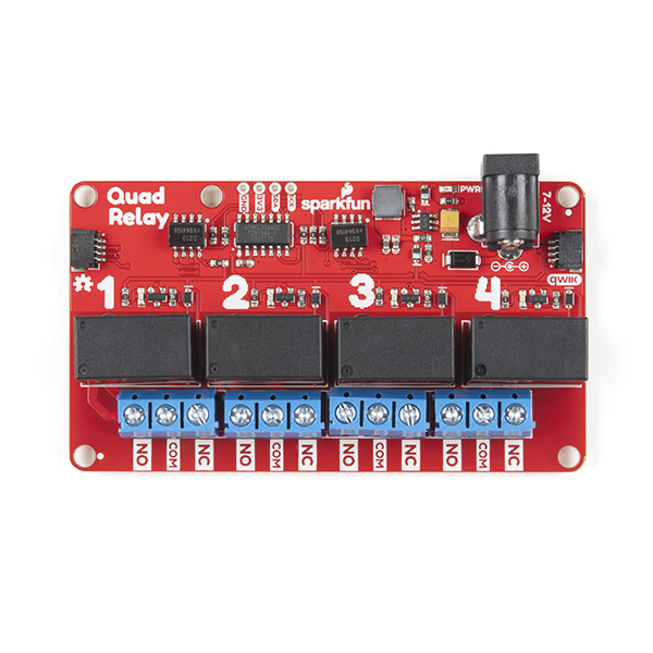
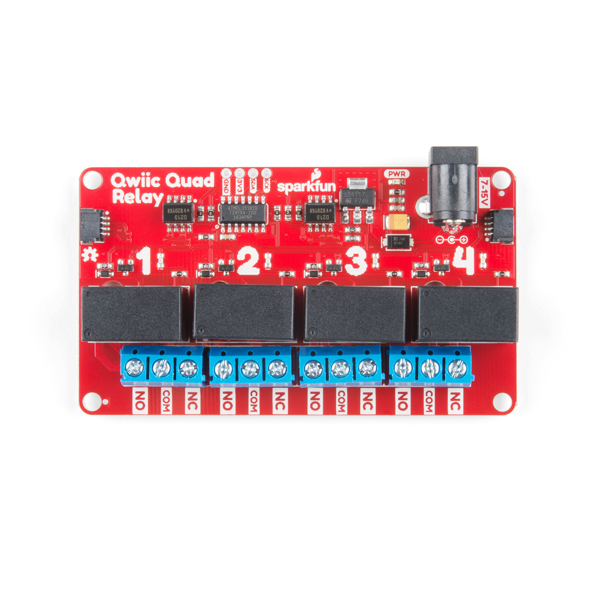
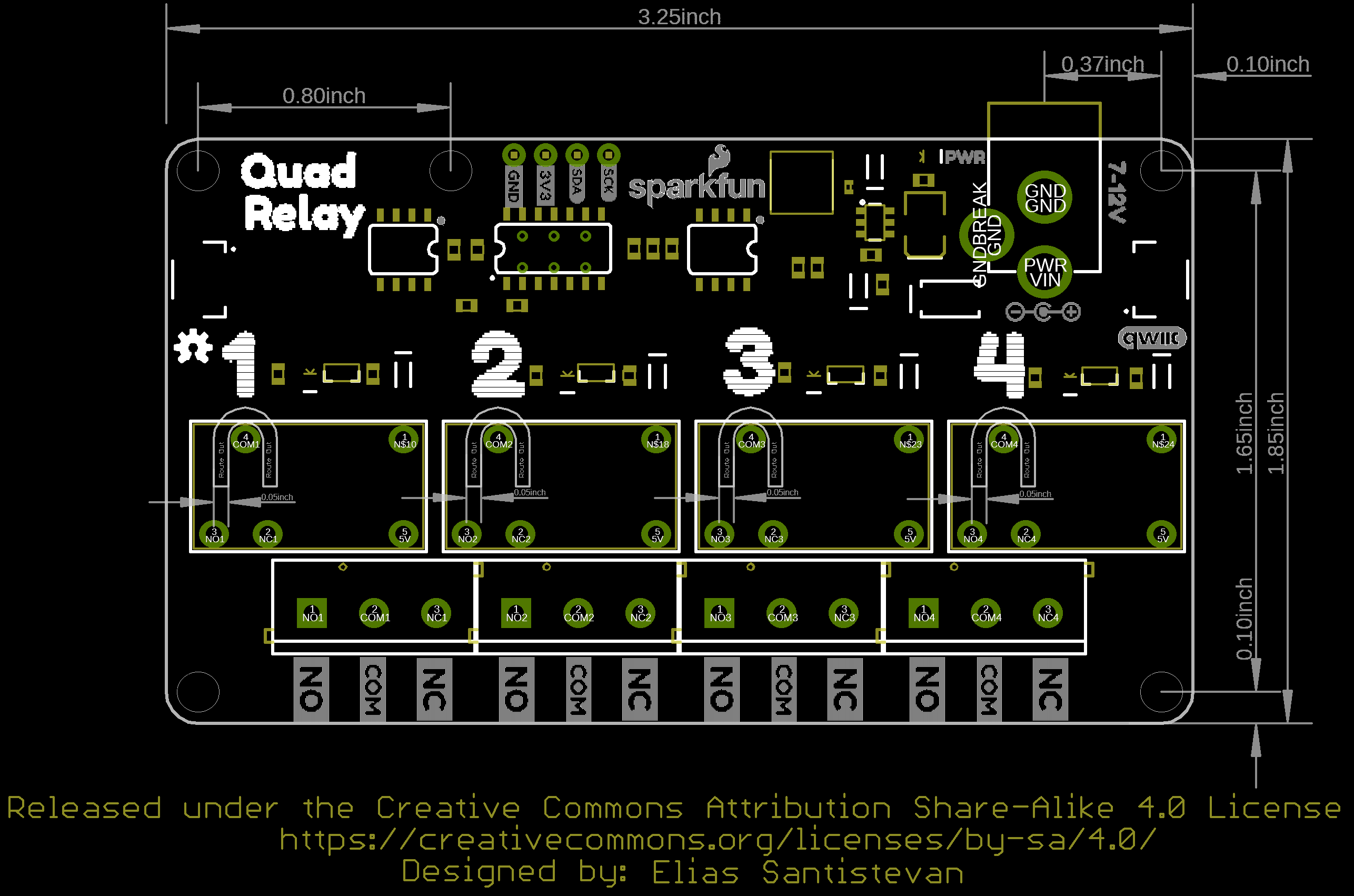
There are two separate power systems on the Quad Relay: a 5V system that powers the relays and a 3.3V system that powers the on board ATtiny84A and interfaces with a microcontroller through the four pin header or Qwiic connector.
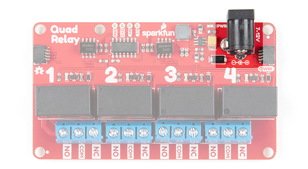
The on board barrel jack takes a power source in a range of 7-12V. It regulates the voltage and supplies power to the 5V power system of the relays. If your wall adapter or power source is at 5 volts like our 5V/2A Wall adapter then you can close the jumper on the underside of the product labeled 5V Wall Adapter (see Jumpers section below), and this will allow you to sidestep the on board regulator to power the 5V system directly. If you decide to go with a higher voltage wall adapter, be cognizant that the voltage regulator will start to heat up. With all the relay channels turned on the Quad Relay will pull ~250mA of current and at 9 Volts, that's 2.25 Watts of power (mathematical!). Over time the regulator will get hot, but will remain functional. I suggest that if you expect to have all relay channels on for extended periods of time, that you go with a 5V power supply.
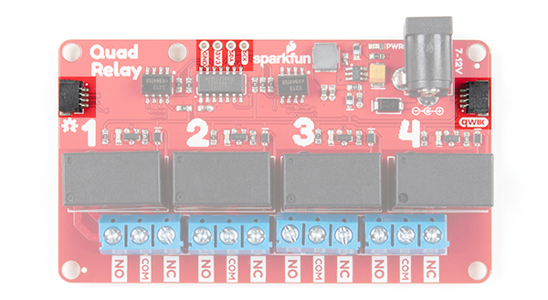
To provide 3.3V to the on board ATtiny84A you can use the plated through hole labeled 3V3 on the four pin header. Alternatively, you can plug a Qwiic connector into one of the two Qwiic connectors.
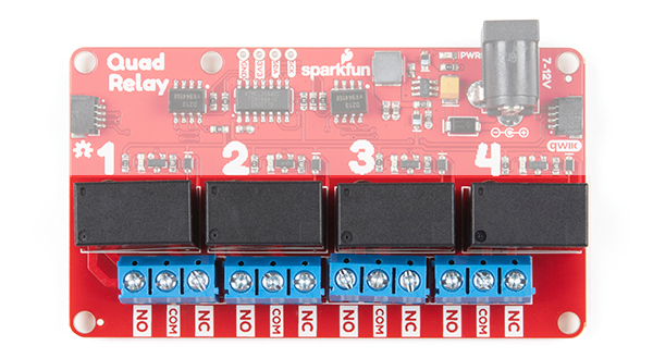
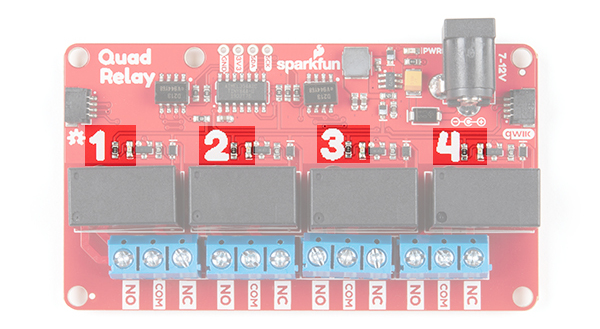
Relays
There are four single pole, double throw JZC-11F relays on the Qwiic Quad Relay. Each relay is capable of 5 Amps at 250VAC or 30VDC. These relays have an associated blue screw pin terminals that are aligned in order from left to right.
LEDs
There is a red power LED labeled PWR that indicates power from the barrel jack. There is also a blue stat LED for each relay labeled with their respective number 1-4. Whenever a relay is activated (i.e. when COM is connected to NO), the respective LED will light up.
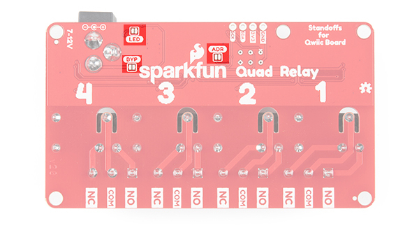
Jumpers
There are three jumpers on the underside of the Qwiic Quad Relay.
- LED - The first jumper is for the power LED. Close the jumper to eanble the power LED.
- ADDR - The second is the address jumper that changes the default I2C address from 0x6D to 0x6C.
- BYP - The thirdis the jumper labeled 5V Wall Adapter Jumper. If you intend to use a wall adapter or other power source that is below 7-15V than you can close this jumper to side step the on board voltage regulator, and provide 5V directly to the 5V power system.
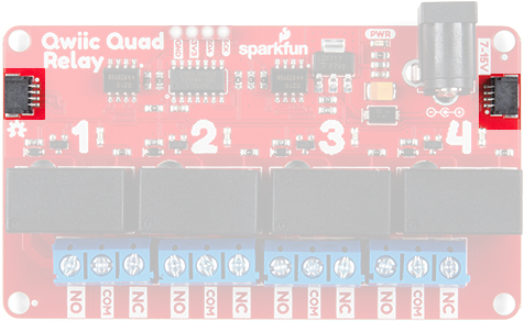
Qwiic Connectors
The Qwiic connectors allow you to integrate easily into our Qwiic environment and allows you to prototype without the need for soldering! The 3.3V provided by the Qwiic connector will power the on board ATtiny84A. If you do not power the 3.3V power system this way, you can still provide power through the four pin header.
Board Dimensions
The board size is 3.25"x 1.85". There are 5x mounting holes on the board, four of which are on each corner of the board. The fifth mounting hole near the upper left of the board is included should you decide to attach a Qwiic enabled device using the 1.0"x1.0" sized board.
Safety Considerations
This product is designed to switch high power AC or DC and so has some inherent dangers. We've done our best to implement safety features directly into the design. To begin, the copper ground pour for the ATtiny84A circuitry is restricted to an area apart from the relays. In regards to the microcontroller, there are opto-isolators that isolate the 3.3V power system that it utilizes from the 5V power system of the relays. Next, the common pin of the relays have an air gap surrounding the pin on three sides to prevent any high voltage arcing. Finally, the traces on the relays are extra wide to handle the high amperage carrying potential of the relays.