Qwiic Quad Relay Hookup Guide
 Elias The Sparkiest
Hardware Assembly
Introduction to Relays
Let's walk through how to setup the relay to switch on a lamp or other device, but let's begin with a short introduction into relays. A relay is a switch. However, unlike most switches, within the relay's housing there is also a switching mechanism that is isolated from the switch. This is the relay's defining feature because this separation between switching mechanism and switch, as well as the switching mechanism's low-power requirements, allows for low-power microcontrollers to activate the switching mechanism without interfacing with whatever is getting "switched". Shmow-zow!
We have three channels per relay broken out to blue screw pin terminals. The channels are labeled for their function. One is considered normally open or NO, the next channel is common or COM, and the final is normally closed or NC. The names explain the state of the channel with relation to the switch at rest. The normally closed channel is where the switch sits before the switching mechanism has been activated and conversely the normally open channel is where the switch would sit after. The common channel is, as the name implies, what the other two channels have in common. This is known as a single pole, double throw switch (SPDT). The image below helps to illustrate this characteristic of our particular relay.
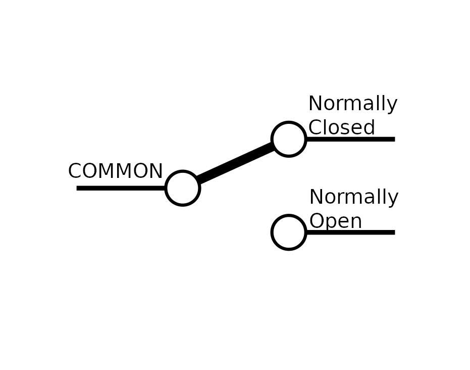
When the switching mechanism is activated the thicker bar in the image above that connects normally closed to common flips over to connect normally open and common.
Assembly
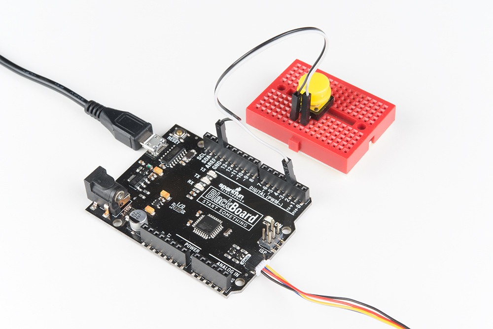
Onto the assembly. First, I'm using a BlackBoard for it's Qwiic capabilities and it's powered via micro-USB. I have a button plugged into a breadboard, straddling the gap in the center, and jumper wires connecting it to pin 2 and GND on the blackboard.
On the tail end is a Qwiic connector leading to the Quad Relay.
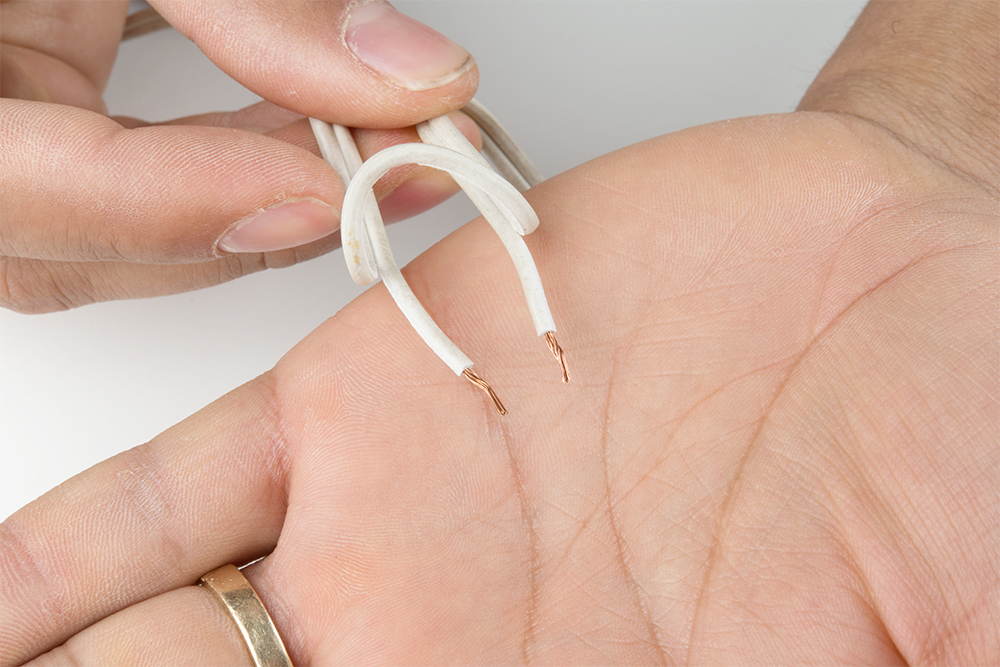
Let's take a quick look at the lamp wire, before we look at the Quad Relay. Our goal here is to sever one of the two lamp wires, and plug the two ends of the cut wire into the relay which will reconnect the wire when we activate the switching mechanism. First, I've cut one of the two wires as shown to create a break in the connection.

I then peeled the wire apart and stripped the two ends.
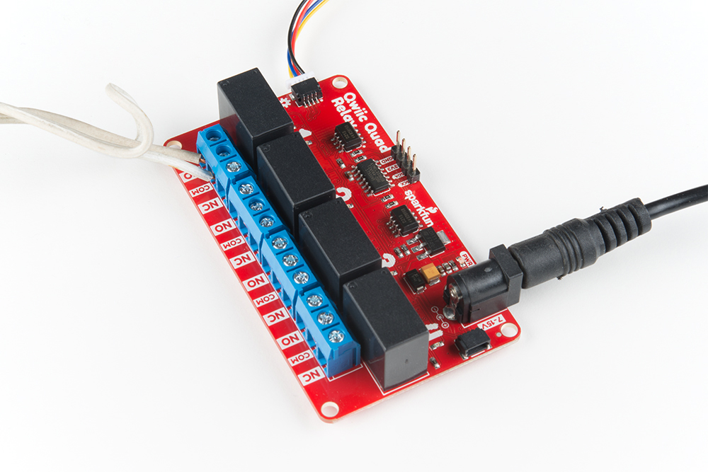
We'll put one end of our wire in the COM channel, and the other we'll have to decide upon. For this project we want our switch to act intuitively: when you activate the switching mechanism, the light switches on. There could be a case where you want the switching mechanism activated as its "rest" state. Since we're going with a more normal approach we'll cut our wire and place one end in common and the other in the normally open channel. Now when we activate the switching mechanism, the severed wire will be reconnected when the switch flips to the normally open channel connecting it and the common channel.
For the quad relay, I'm powering the 5V system (the relays), with a 5V Wall Adapter, and the 5V Wall Adapter jumper closed underneath. The Qwiic cable from the black board is providing power to the 3.3V system as seen at the top of the picture below, and we have the lamp cable plugged into and the screw terminals tightened down on channels COM and NO.
Looking for information about safety and insulation? Check out the notes about Safety and Insulation from our Beefcake Relay Control Kit.
Now that our hardware is all set up, let's take a look at the code that turns the lamp on. Remember to not touch the relay's contacts when the system is powered.